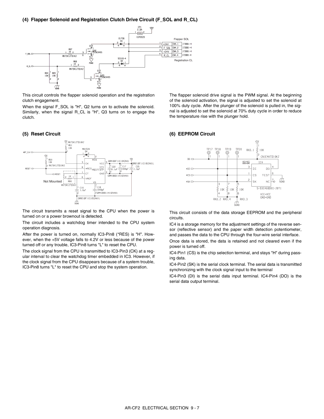
(4) Flapper Solenoid and Registration Clutch Drive Circuit (F_SOL and R_CL)
Flapper SOL
Registration CL
This circuit controls the flapper solenoid operation and the registration clutch engagement.
When the signal F_SOL is "H", Q2 turns on to activate the solenoid. Similarly, when the signal R_CL is "H", Q3 turns on to engage the clutch.
The flapper solenoid drive signal is the PWM signal. At the beginning of the solenoid activation, the signal is adjusted to set the solenoid at 100% duty cycle. After the plunger of the solenoid is pulled in, the sig- nal is adjusted to set the solenoid at 70% duty cycle in order to reduce the temperature rise with the plunger hold.
(5) Reset Circuit | (6) EEPROM Circuit |
Not Mounted
The circuit transmits a reset signal to the CPU when the power is turned on or a power brownout is detected.
The circuit includes a watchdog timer intended to the CPU system operation diagnosis.
After the power is turned on, normally
The clock signal from the CPU is transmitted to
This circuit consists of the data storage EEPROM and the peripheral circuits.
IC4 is a storage memory for the adjustment settings of the reverse sen- sor (reflective sensor) and the paper width detection potentiometer, and passes the data to the CPU through the
Once data is stored, the data is retained and not cleared even if the power is turned off.