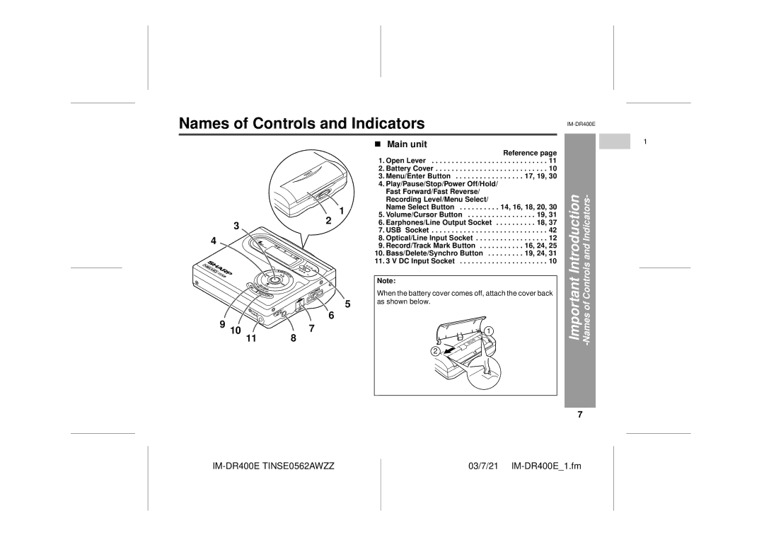
Names of Controls and Indicators
![]() 1
1
32
4
5
6
9 10 | 7 |
11 | 8 |
! Main unit |
|
| Reference page |
1. Open Lever | . . . . . . . . . . . 11 |
2. Battery Cover | . . . . . . . . . . . 10 |
3. Menu/Enter Button | . . . . . 17, 19, 30 |
4.Play/Pause/Stop/Power Off/Hold/ Fast Forward/Fast Reverse/
Recording Level/Menu Select/ |
|
Name Select Button | 14, 16, 18, 20, 30 |
5. Volume/Cursor Button | . . . . . . . . . 19, 31 |
6. Earphones/Line Output Socket . | . . . . . . . . . 18, 37 |
7. USB Socket | . . . . . . . . . . . . 42 |
8. Optical/Line Input Socket | . . . . . . . . . . . . 12 |
9. Record/Track Mark Button | . . . . . . 16, 24, 25 |
10. Bass/Delete/Synchro Button . . . | . . . . . . 19, 24, 31 |
11. 3 V DC Input Socket | . . . . . . . . . . . . 10 |
Note:
When the battery cover comes off, attach the cover back as shown below.
1
2
Important Introduction -Names of Controls and Indicators-
7
1
6
5
4
3
2
1
