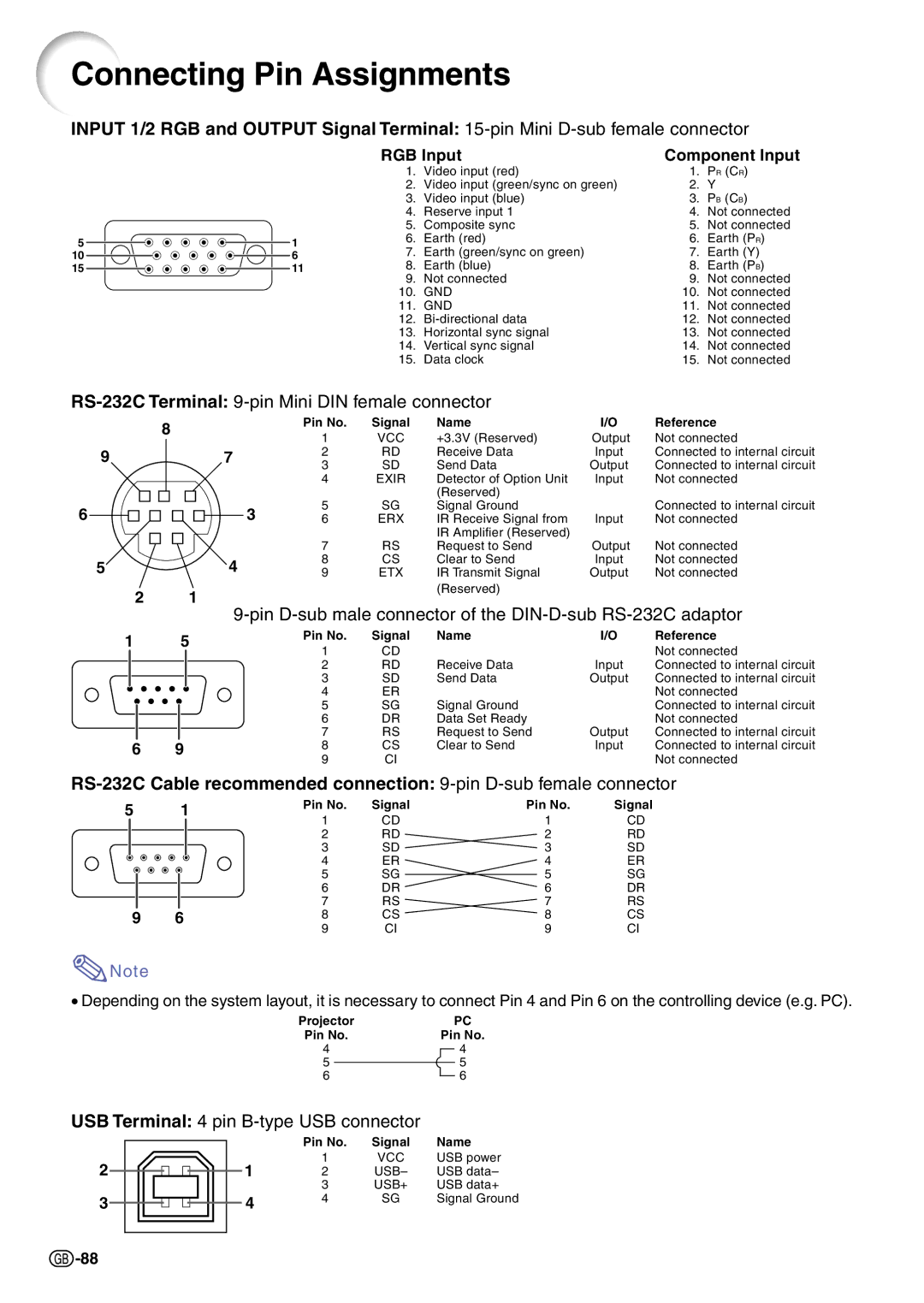
Connecting Pin Assignments
INPUT 1/2 RGB and OUTPUT Signal Terminal:
|
|
|
|
|
|
| RGB Input | Component Input | ||
|
|
|
|
|
|
| 1. | Video input (red) | 1. | PR (CR) |
|
|
|
|
|
|
| 2. | Video input (green/sync on green) | 2. | Y |
|
|
|
|
|
|
| 3. | Video input (blue) | 3. | PB (CB) |
|
|
|
|
|
|
| 4. | Reserve input 1 | 4. | Not connected |
|
|
|
|
|
|
| 5. | Composite sync | 5. | Not connected |
5 |
|
|
|
|
| 1 | 6. | Earth (red) | 6. | Earth (PR) |
|
|
|
| 7. | Earth (green/sync on green) | 7. | Earth (Y) | |||
10 |
|
|
| 6 | ||||||
|
| |||||||||
15 |
|
|
| 11 | 8. | Earth (blue) | 8. | Earth (PB) | ||
|
| |||||||||
|
|
|
|
|
|
| 9. | Not connected | 9. | Not connected |
|
|
|
|
|
|
| 10. | GND | 10. | Not connected |
|
|
|
|
|
|
| 11. | GND | 11. | Not connected |
|
|
|
|
|
|
| 12. | 12. | Not connected | |
|
|
|
|
|
|
| 13. | Horizontal sync signal | 13. | Not connected |
|
|
|
|
|
|
| 14. | Vertical sync signal | 14. | Not connected |
|
|
|
|
|
|
| 15. | Data clock | 15. | Not connected |
RS-232C Terminal: 9-pin Mini DIN female connector
|
|
| 8 |
|
| Pin No. | Signal | Name | I/O | Reference |
|
|
|
|
| 1 | VCC | +3.3V (Reserved) | Output | Not connected | |
|
|
|
|
|
| |||||
9 |
|
| 7 | 2 | RD | Receive Data | Input | Connected to internal circuit | ||
|
| 3 | SD | Send Data | Output | Connected to internal circuit | ||||
|
|
|
|
|
| |||||
|
|
|
|
|
| 4 | EXIR | Detector of Option Unit | Input | Not connected |
|
|
|
|
|
|
|
| (Reserved) |
|
|
6 |
|
| 3 | 5 | SG | Signal Ground |
| Connected to internal circuit | ||
|
| 6 | ERX | IR Receive Signal from | Input | Not connected | ||||
|
|
|
|
|
|
|
| IR Amplifier (Reserved) |
|
|
|
|
|
|
|
| 7 | RS | Request to Send | Output | Not connected |
5 |
|
| 4 | 8 | CS | Clear to Send | Input | Not connected | ||
|
| 9 | ETX | IR Transmit Signal | Output | Not connected | ||||
2 | 1 |
|
| (Reserved) |
|
| ||||
|
|
|
|
| ||||||
|
|
|
|
|
| |||||
1 |
| 5 | Pin No. | Signal | Name | I/O | Reference | |||
| 1 | CD |
|
| Not connected | |||||
|
|
|
|
|
|
|
| |||
|
|
|
|
|
| 2 | RD | Receive Data | Input | Connected to internal circuit |
|
|
|
|
|
| 3 | SD | Send Data | Output | Connected to internal circuit |
|
|
|
|
|
| 4 | ER |
|
| Not connected |
|
|
|
|
|
| 5 | SG | Signal Ground |
| Connected to internal circuit |
|
|
|
|
|
|
| ||||
|
|
|
|
|
| 6 | DR | Data Set Ready |
| Not connected |
|
|
|
|
|
| 7 | RS | Request to Send | Output | Connected to internal circuit |
6 | 9 |
| 8 | CS | Clear to Send | Input | Connected to internal circuit | |||
|
|
|
|
|
| 9 | CI |
|
| Not connected |
5 |
| 1 | Pin No. | Signal | Pin No. | Signal |
| |||
| 1 | CD | 1 | CD |
| |||||
|
|
|
|
|
|
| ||||
|
|
|
|
|
| 2 | RD | 2 | RD |
|
|
|
|
|
|
| 3 | SD | 3 | SD |
|
|
|
|
|
|
| 4 | ER | 4 | ER |
|
|
|
|
|
|
| 5 | SG | 5 | SG |
|
|
|
|
|
|
|
| ||||
|
|
|
|
|
| 6 | DR | 6 | DR |
|
|
|
|
|
|
| 7 | RS | 7 | RS |
|
9 | 6 |
| 8 | CS | 8 | CS |
| |||
|
|
|
|
|
| 9 | CI | 9 | CI |
|
![]() Note
Note
•Depending on the system layout, it is necessary to connect Pin 4 and Pin 6 on the controlling device (e.g. PC).
Projector |
|
| PC | ||||
Pin No. | Pin No. | ||||||
4 |
|
|
|
|
| 4 | |
5 |
|
|
|
|
| 5 | |
|
|
|
|
| |||
6 |
|
|
|
|
|
| 6 |
USB Terminal: 4 pin
2
3
| Pin No. | Signal | Name |
1 | 1 | VCC | USB power |
2 | USB– | USB data– | |
| 3 | USB+ | USB data+ |
4 | 4 | SG | Signal Ground |
|
|
|
![]() -88
-88