Assembly
Driveshaft/Powerhead All Models
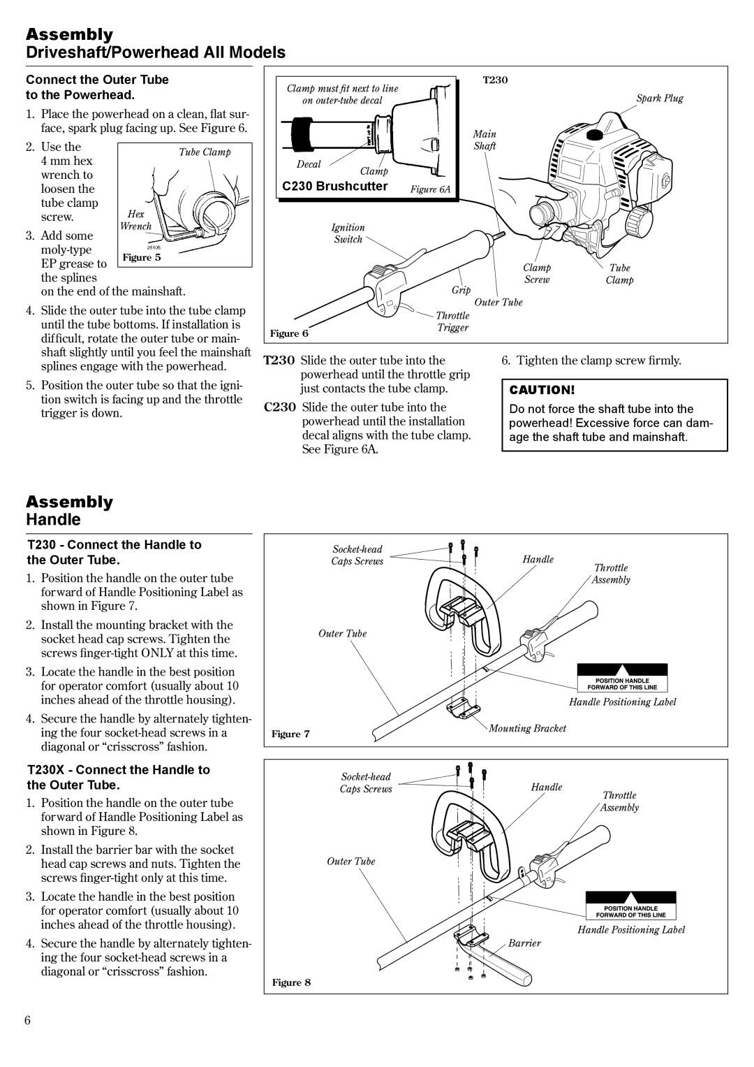
Connect the Outer Tube to the Powerhead.
1.Place the powerhead on a clean, flat sur- face, spark plug facing up. See Figure 6.
2. Use the |
| |
Tube Clamp | ||
4 mm hex | ||
| ||
wrench to |
| |
loosen the |
| |
tube clamp | Hex | |
screw. | ||
3. Add some | Wrench | |
| ||
Figure 5 | ||
EP grease to | ||
| ||
| ||
the splines |
| |
on the end of the mainshaft. | ||
4. Slide the outer tube into the tube clamp until the tube bottoms. If installation is difficult, rotate the outer tube or main- shaft slightly until you feel the mainshaft
Clamp must fit next to line | T230 | ||
Spark Plug | |||
on | |||
|
| Main | |
|
| Shaft | |
Decal | Clamp |
| |
|
| ||
C230 Brushcutter Figure 6A
Ignition
Switch ![]()
ClampTube
ScrewClamp
| Grip |
| Outer Tube |
| Throttle |
Figure 6 | Trigger |
|
splines engage with the powerhead.
5. Position the outer tube so that the igni- tion switch is facing up and the throttle trigger is down.
T230 Slide the outer tube into the powerhead until the throttle grip just contacts the tube clamp.
C230 Slide the outer tube into the powerhead until the installation decal aligns with the tube clamp. See Figure 6A.
6. Tighten the clamp screw firmly.
CAUTION!
Do not force the shaft tube into the powerhead! Excessive force can dam age the shaft tube and mainshaft.
Assembly
Handle
T230 - Connect the Handle to the Outer Tube.
1.Position the handle on the outer tube forward of Handle Positioning Label as shown in Figure 7.
2.Install the mounting bracket with the socket head cap screws. Tighten the screws
3.Locate the handle in the best position for operator comfort (usually about 10 inches ahead of the throttle housing).
4.Secure the handle by alternately tighten- ing the four
T230X - Connect the Handle to the Outer Tube.
1.Position the handle on the outer tube forward of Handle Positioning Label as shown in Figure 8.
2.Install the barrier bar with the socket head cap screws and nuts. Tighten the screws
3.Locate the handle in the best position for operator comfort (usually about 10 inches ahead of the throttle housing).
4.Secure the handle by alternately tighten- ing the four
Handle |
| |
Caps Screws | Throttle | |
|
| |
|
| Assembly |
Outer Tube |
|
|
Handle Positioning Label
Figure 7 | Mounting Bracket |
|
Handle |
| |
Caps Screws | Throttle | |
|
| |
|
| Assembly |
Outer Tube |
|
|
|
| Handle Positioning Label |
| Barrier |
|
Figure 8 |
|
|