L-828 specifications
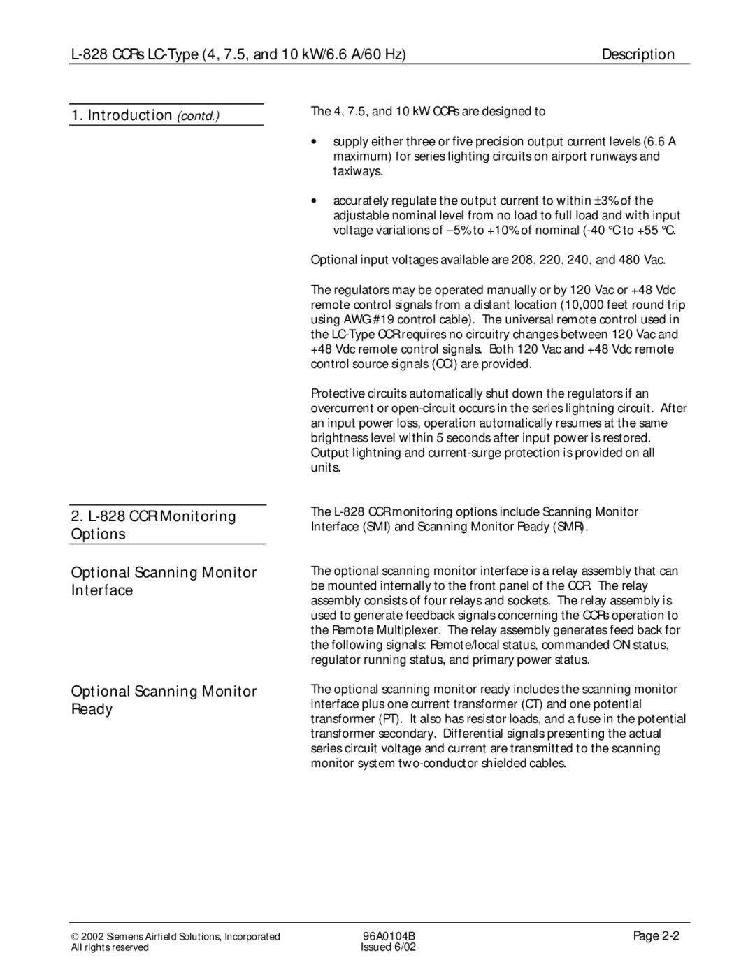
The Siemens L-828 is a state-of-the-art aircraft communication and navigation system that is designed to enhance efficiency and safety in aviation operations. This system is equipped with a range of advanced features that cater to the evolving needs of modern air traffic management and avionics.One of the standout characteristics of the L-828 is its versatile communication capabilities. It incorporates VHF and UHF radio systems, enabling flexible and reliable communication between pilots, air traffic controllers, and other aircraft. The system supports both voice communication and data link services, ensuring that critical information is exchanged seamlessly during flight operations.
In terms of navigation, the Siemens L-828 is equipped with cutting-edge Global Navigation Satellite System (GNSS) technology. This allows for precise positioning and navigation, essential for modern pilotage in complex airspace environments. With built-in performance monitoring, the system can also provide predictive analytics, which enhances situational awareness for pilots and ground controllers.
The architecture of the L-828 is designed for ease of integration with existing aircraft systems. Its modular design allows for straightforward upgrades and the incorporation of additional functionalities as aviation technology continues to evolve. This adaptability ensures that operators can extend the lifespan of their investment by easily implementing new features without requiring a complete system overhaul.
Another key feature of the Siemens L-828 is its robust cybersecurity measures. In an era where the threat of cyberattacks is growing, the system employs advanced encryption techniques and authentication protocols to safeguard sensitive communications and data. This emphasis on security ensures that both operational integrity and passenger safety are maintained.
Moreover, the Siemens L-828 has user-friendly interfaces that reduce pilot workload and enhance overall flight experience. With intuitive controls and clear displays, pilots can easily access critical information, thereby facilitating smoother and safer flight operations.
In conclusion, the Siemens L-828 represents a significant advancement in aviation communication and navigation technology. Its combination of versatile communication capabilities, advanced navigation systems, modular design, and heightened security protocols makes it a crucial tool for modern aircraft. As the aviation industry continues to evolve, systems like the L-828 will undoubtedly play an indispensable role in optimizing flight operations and ensuring safety in the skies.

