4-3.DC mode
1.Selection of bar length
・Select the length applicable to work size base on static charge elimination area and static charge elimination characteristics.
2. | Installation of body |
|
| ・Keep the distance between the ionizer and charged objects within 50 to 2000mm. Although the ionizer | |
| can be mounted outside of this range, it may not operate properly depending on the operating conditions. | |
| Therefore, be sure to check if the ionizer will operate properly. | |
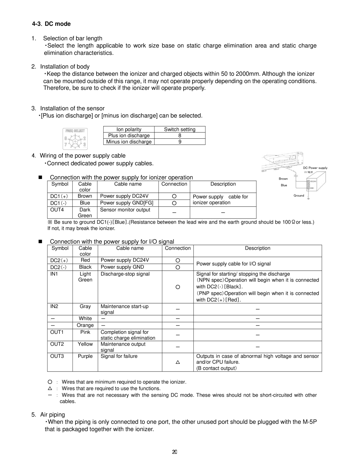
3. | Installation of the sensor |
|
| ・[Plus ion discharge] or [minus ion discharge] can be selected. | |
| Ion polarity | Switch setting |
| Plus ion discharge | 8 |
| Minus ion discharge | 9 |
4.Wiring of the power supply cable
・Connect dedicated power supply cables.
Connection with the power supply for ionizer operation
Symbol | Cable | Cable name | Connection | Description | ||
|
|
| color |
|
|
|
( |
| ) | Brown | Power supply DC24V | ○ | Power supply cable for |
DC1 + |
|
|
|
| ||
( | ) | Blue | Power supply GND[FG] | ○ | ionizer operation | |
DC1 - |
|
|
|
| ||
OUT4 |
|
| Dark | Sensor monitor output | - | - |
|
|
| Green |
| ||
|
|
|
|
|
| |
DC Power supply
Brown
Blue
Ground
※Be sure to ground
Connection with the power supply for I/O signal
Symbol | Cable | Cable name | Connection |
| color |
|
|
DC2(+) | Red | Power supply DC24V | ○ |
Black | Power supply GND | ○ | |
IN1 | Light |
| |
| Green |
|
|
|
|
| ○ |
|
|
|
|
IN2 | Gray | Maintenance | - |
|
| signal | |
|
|
| |
- | White | - | - |
- | Orange | - | - |
OUT1 | Pink | Completion signal for | - |
|
| static charge elimination | |
|
|
| |
OUT2 | Yellow | Maintenance output | - |
|
| signal | |
|
|
| |
OUT3 | Purple | Signal for failure |
|
|
|
| △ |
|
|
|
|
Description
Power supply cable for I/O signal
Signal for starting/ stopping the discharge
(NPN spec)Operation will begin when it is connected with
(PNP spec)Operation will begin when it is connected with DC2(+)[Red].
-
-
-
-
-
Outputs in case of abnormal high voltage and sensor and/or CPU failure.
(B contact output)
○: Wires that are minimum required to operate the ionizer. △ : Wires that are required to use the functions.
- : Wires that are not necessary with the sensing DC mode. These wires should not be
5.Air piping
・When the piping is only connected to one port, the other unused port should be plugged with the
20