Auto balance sensor
Horizontally place the auto balance sensor under the ionizer and face its metal plate upward. Because
the ion balance will be changed depending on the installation height, install the sensor on the same level with a workpiece as much as possible. The auto balance sensor can be removed once the ion balance adjustment is completed.
Keep the height between the auto balance sensor and ionizer within the installation height stated in
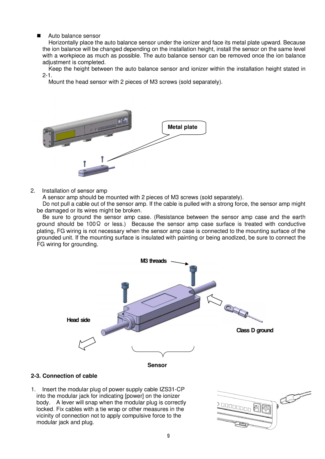
Mount the head sensor with 2 pieces of M3 screws (sold separately).
Metal plate
2.Installation of sensor amp
A sensor amp should be mounted with 2 pieces of M3 screws (sold separately).
Do not pull a cable out of the sensor amp. If the cable is pulled with a strong force, the sensor amp might
be damaged or its wires might be broken.
Be sure to ground the sensor amp case. (Resistance between the sensor amp case and the earth ground should be 100Ω or less.) Because the sensor amp case surface is treated with conductive plating, FG wiring is not necessary when the sensor amp case is connected to the mounting surface of the grounded unit. If the mounting surface is insulated with painting or being anodized, be sure to connect the FG wiring for grounding.
M3 threads
Head side
Class D ground
Sensor
1.Insert the modular plug of power supply cable
9