6.Be sure to ground the DC1
If the lead wire is not grounded, the ion balance will be unstable, and an electric shock may occur. At the same time, the ionizer and power supply might be damaged.
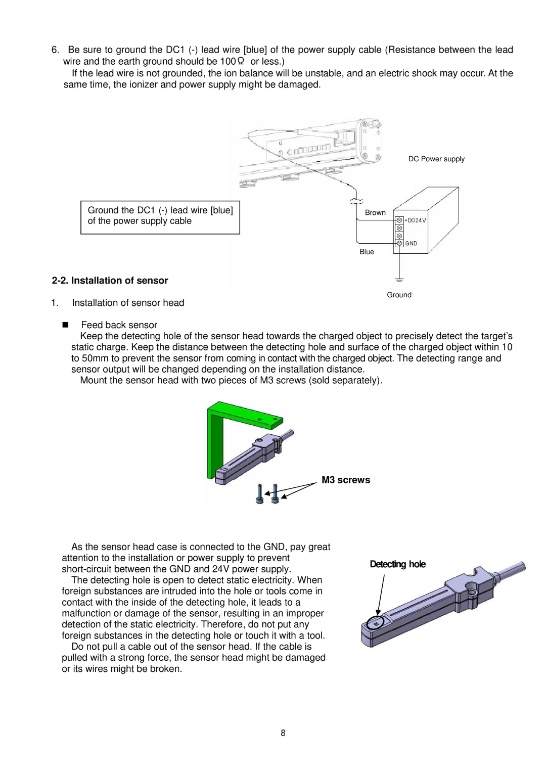
Ground the DC1
2-2. Installation of sensor
1.Installation of sensor head
DC Power supply
Brown
Blue
Ground
Feed back sensor
Keep the detecting hole of the sensor head towards the charged object to precisely detect the target’s static charge. Keep the distance between the detecting hole and surface of the charged object within 10 to 50mm to prevent the sensor from coming in contact with the charged object. The detecting range and sensor output will be changed depending on the installation distance.
Mount the sensor head with two pieces of M3 screws (sold separately).
M3 screws
As the sensor head case is connected to the GND, pay great attention to the installation or power supply to prevent
foreign substances are intruded into the hole or tools come in contact with the inside of the detecting hole, it leads to a malfunction or damage of the sensor, resulting in an improper detection of the static electricity. Therefore, do not put any foreign substances in the detecting hole or touch it with a tool.
Do not pull a cable out of the sensor head. If the cable is pulled with a strong force, the sensor head might be damaged or its wires might be broken.
8