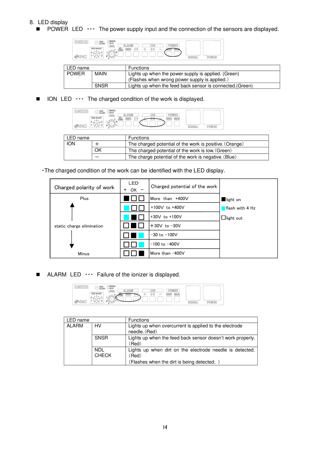
8.LED display
POWER LED ・・・ The power supply input and the connection of the sensors are displayed.
LED name |
| Functions |
POWER | MAIN | Lights up when the power supply is applied. (Green) |
|
| (Flashes when wrong power supply is applied.) |
| SNSR | Lights up when the feed back sensor is connected.(Green) |
ION LED ・・・ The charged condition of the work is displayed.
LED name |
| Functions |
ION | + | The charged potential of the work is positive.(Orange) |
| OK | The charged potential of the work is low.(Green) |
| - | The charge potential of the work is negative.(Blue) |
・The charged condition of the work can be identified with the LED display.
Charged polarity of work | LED |
| Charged potential of the work |
|
+ OK | - |
| ||
|
|
| ||
Plus | ■□□ More than +400V | ■light on | ||
| ■□□ +100V to +400V | ■flash with 4 Hz | ||
| ■■□ +30V to +100V | □light out | ||
static charge elimination | □■□ +30V to |
| ||
| □■■ |
| ||
| □□■ |
| ||
Minus | □□■ More than |
| ||
ALARM LED ・・・ Failure of the ionizer is displayed.
LED name |
| Functions |
ALARM | HV | Lights up when overcurrent is applied to the electrode |
|
| needle.(Red) |
| SNSR | Lights up when the feed back sensor doesn’t work properly. |
|
| (Red) |
| NDL | Lights up when dirt on the electrode needle is detected. |
| CHECK | (Red) |
|
| (Flashes when the dirt is being detected. ) |
14