Operation
A safe collection area should be located where children, pets, and bystanders will not come into contact with chipped material as it is being discharged, or be hit by deflected pieces that may ricochet away from the collec- tion area with great force.
When using direct discharge, check the discharge area frequently for accumulation of material near the dis- charge port, and make sure the material can be safely ejected away from the unit. Letting material accumulate directly in front of the units discharge port may cause a jam.
Direct Discharge Blowing
The direct discharge method of clearing debris can also be used to clear driveways or other large areas. Make sure the discharge deflector elbow is directed to one side of the unit, then blow debris away from the center of the area toward the outer edges.
Do not discharge against a fence or wall where dis- charged material may deflect back toward you and pos- sibly cause injury. If a wall, fence, or other obstacle is encountered while clearing an area, stop the unit, change the direction of the discharge stream, and blow debris away from the obstruction.
AWARNING
Never attempt to move the unit while material is in chipper cone being chipped.
Always allow limbs and branches to be completely processed before engaging the power drive bail lever.
Failure to obey these instructions may result in jamming of the chipper, or erratic power drive per- formance causing sudden starting and stopping of the power drive.
off and allow the rotor to come to a complete stop.
Never start the unit without securely attaching the discharge bag or installing the discharge elbow in a safe direction. Failure to obey these instructions may result in serious injury.
OPERATOR AUADJUSTMENTSI”-‘l
Three differentt suction controlcontror settingssenrngs and three nozzle height positions provide a total of nine different![]() positions for handling virtually any type of lawn surface and yard
positions for handling virtually any type of lawn surface and yard
![]() 1waste conditions.
1waste conditions.
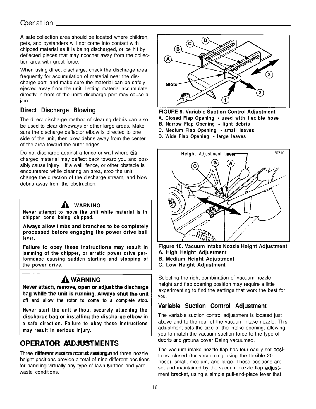
FIGURE 9. Variable Suction Control Adjustment A. Closed Flap Opening  - used with flexible hose B. Narrow Flap Opening
 -
light debris
C. Medium Flap Opening ![]() - small leaves D. Wide Flap Opening
- small leaves D. Wide Flap Opening ![]() - large leaves
- large leaves
Height Adjustment Lever
/;;\ a7
Figure 10. Vacuum Intake Nozzle Height Adjustment A. High Height Adjustment
B. Medium Height Adjustment
C. Low Height Adjustment
Selecting the right combination of vacuum nozzle height and flap opening position may require a little experimenting to find the settings that work the best for you.
Variable Suction Control Adjustment
The variable suction control adjustment is located just above and to the rear of the vacuum intake nozzle. This adjustment sets the size of the intake opening, allowing
you to match the vacuum suction force to the type of 1..
aeDnS ana grouna cover Deing vacuumed.
The vacuum intake nozzle flap has four
1 6