![]() SM 2610008289
SM 2610008289
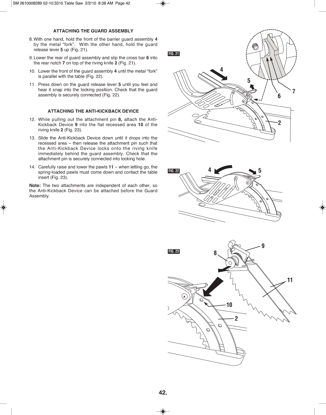
ATTACHING THE GUARD ASSEMBLY
8.With one hand, hold the front of the barrier guard assembly 4 by the metal “fork”. With the other hand, hold the guard release lever 5 up (Fig. 21).
9.Lower the rear of guard assembly and slip the cross bar 6 into the rear notch 7 on top of the riving knife 2 (Fig. 21).
10.Lower the front of the guard assembly 4 until the metal “fork” is parallel with the table (Fig. 22).
11.Press down on the guard release lever 5 until you feel and hear it snap into the locking position. Check that the guard assembly is securely connected (Fig. 22).
ATTACHING THE ANTI-KICKBACK DEVICE
12.While pulling out the attachment pin 8, attach the Anti- Kickback Device 9 into the flat recessed area 10 of the riving knife 2 (Fig. 23).
13.Slide the
14.Carefully raise and lower the pawls 11 – when letting go, the
Note: The two attachments are independent of each other, so the
FIG. 21
FIG. 22
FIG. 23
4
5
7
6
![]() 2
2
4 | 5 |
![]()
![]() 9 8
9 8 ![]()
![]()
![]()
11
![]() 10
10
![]() 2
2
42.