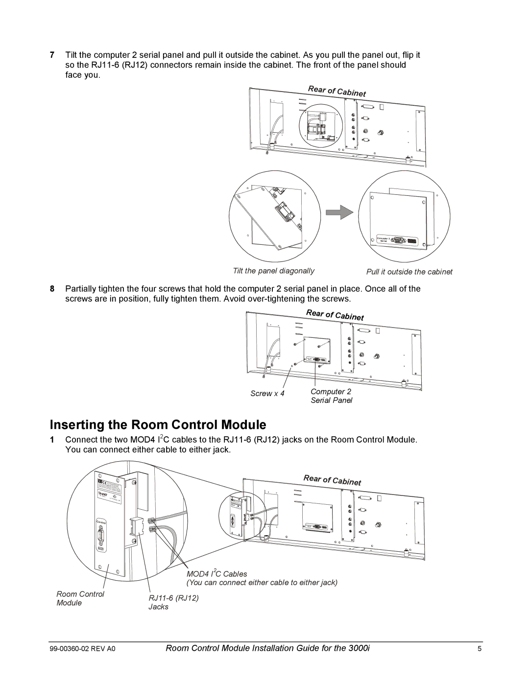
7Tilt the computer 2 serial panel and pull it outside the cabinet. As you pull the panel out, flip it so the
Rear of Cabinet
Tilt the panel diagonally | Pull it outside the cabinet |
8Partially tighten the four screws that hold the computer 2 serial panel in place. Once all of the screws are in position, fully tighten them. Avoid
Rear of Cabinet
Screw x 4 | Computer 2 |
| Serial Panel |
Inserting the Room Control Module
1Connect the two MOD4 I2C cables to the
iCmntaueusrstfeearchecanecrmpetftuahlnaiytntimnetraTpOfeeyharpfrirectseear1rndaeu5ctensievoceo,inefcautienrnhseddcescoe(eFum2siiCbv)rpejeCeTldicdeh,trisuoistnlopwedcetlsieurth.hvadeitiicnoegn.
on the Room Control Module.
Rear of Cabinet
| MOD4 I2C Cables | |
| (You can connect either cable to either jack) | |
Room Control | ||
Module | ||
Jacks | ||
|
Room Control Module Installation Guide for the 3000i | 5 |