Installing the Room Control Module
These instructions explain how to install the SMART Room Control Module (part No.
You can use a
NOTE: Check that the last four digits of the serial number for your 3000i are greater than 05000. The Room Control Module only works with SMART Board 3000i interactive whiteboards that have a serial number greater than 05000, because these units contain the SMART
The Room Control Module kit for the 3000i contains the following:
•the Room Control Module
•a custom
•a custom I2C flash adapter cable (part No.
•an
•the warranty document
•a diskette with the hex file for upgrading the control panel firmware
•the Room Control Module Installation Guide and Room Control Module Integrator’s Guide
You’ll need a Phillips® No. 2 screwdriver and cutting pliers or wire cutters to perform the installation.
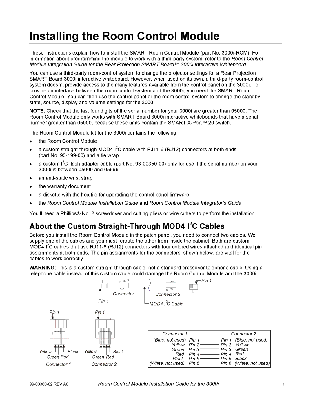
About the Custom Straight-Through MOD4 I2C Cables
Before you install the Room Control Module in the patch panel, you need to connect two cables. We supply one of the cables and you must reroute the other from inside the cabinet. Both are custom MOD4 I2C cables that use
WARNING: This is a custom
|
| Connector 1 |
|
|
| Pin 1 |
|
|
|
|
| ||
|
|
| Connector 2 | |||
|
|
| ||||
| Pin 1 |
| MOD4 I2C Cable | |||
|
| |||||
Pin 1 | Pin 1 |
|
|
|
| |
|
|
|
|
|
|
|
|
|
|
|
|
|
|
|
|
|
|
|
| Connector 1 |
| Connector 2 | ||
|
|
|
|
|
|
|
|
|
|
|
|
|
|
|
|
|
|
|
|
| ||||
|
|
|
|
|
|
|
|
|
|
|
|
|
|
|
|
|
|
|
|
| ||||
|
|
|
|
|
|
|
|
|
|
|
|
|
|
|
|
|
|
|
|
| ||||
|
|
|
|
|
|
|
|
|
|
|
|
|
|
|
|
|
|
|
|
| ||||
|
|
|
|
|
|
|
|
|
|
|
|
|
|
|
|
|
|
|
| (Blue, not used) | Pin 1 | Pin 1 | (Blue, not used) | |
|
|
|
|
|
|
|
|
|
|
|
|
|
|
|
|
|
|
|
| |||||
|
|
|
|
|
|
|
|
|
|
|
|
|
|
|
|
|
|
|
| Yellow | Pin 2 | Pin 2 | Yellow | |
|
|
|
|
|
|
|
|
|
|
|
|
|
|
|
|
|
|
|
| |||||
Yellow |
|
|
|
|
|
| Black | Yellow |
|
|
|
|
|
| Black | Green | Pin 3 | Pin 3 | Green | |||||
|
|
|
|
|
|
|
|
|
|
|
| |||||||||||||
|
|
|
|
|
|
|
|
|
|
|
| Red | Pin 4 | Pin 4 | Red | |||||||||
|
|
|
|
|
| |||||||||||||||||||
Green Red | Green Red | |||||||||||||||||||||||
Black | Pin 5 | Pin 5 | Black | |||||||||||||||||||||
Connector 1 | Connector 2 | (White, not used) | Pin 6 | Pin 6 (White, not used) | ||||||||||||||||||||
Room Control Module Installation Guide for the 3000i | 1 |