NW-A805/A806/A808/NWZ-A815/A816/A818
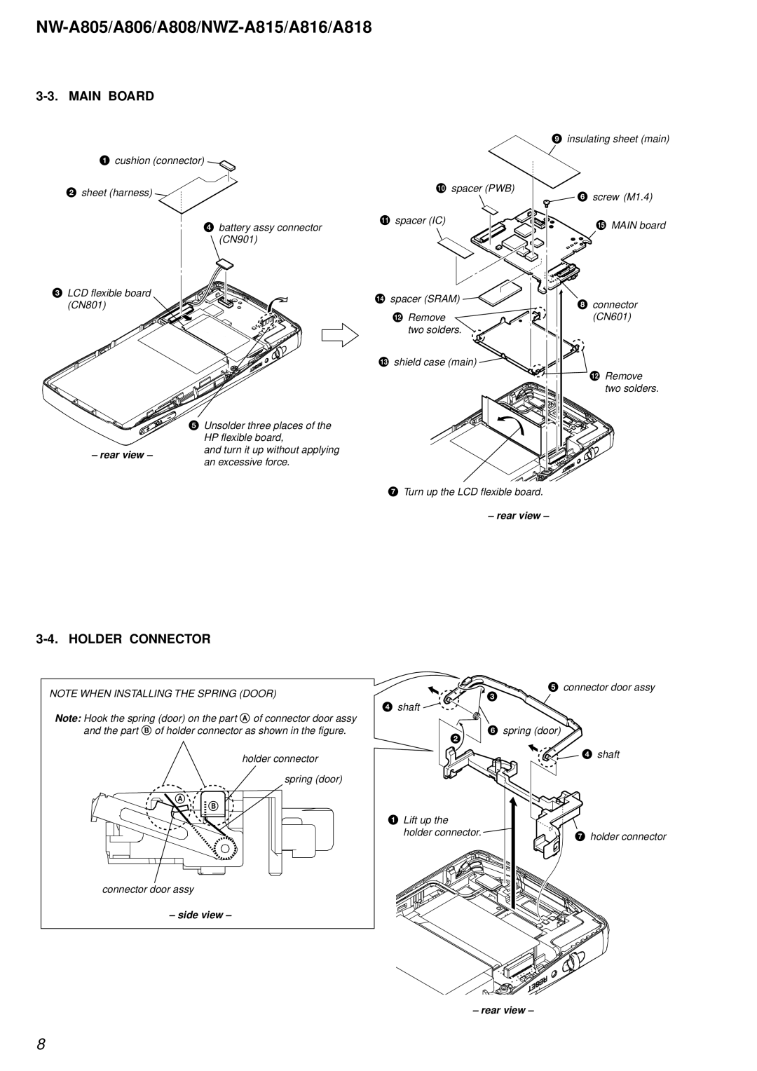
3-3. MAIN BOARD
1cushion (connector) ![]()
2sheet (harness) ![]()
4 battery assy connector (CN901)
3LCD flexible board
(CN801)
5 Unsolder three places of the HP flexible board,
– rear view –and turn it up without applying an excessive force.
9 insulating sheet (main)
q; spacer (PWB)
| 6 screw (M1.4) |
qa spacer (IC) | qg MAIN board |
| |
qf spacer (SRAM) | 8 connector |
| |
qs Remove | (CN601) |
two solders. |
|
qd shield case (main) |
|
| qs Remove |
| two solders. |
7Turn up the LCD flexible board.
–rear view –
3-4. HOLDER CONNECTOR
NOTE WHEN INSTALLING THE SPRING (DOOR)
Note: Hook the spring (door) on the part A of connector door assy and the part B of holder connector as shown in the figure.
5 connector door assy
3
4 shaft ![]()
6 spring (door) |
2 |
4 shaft |
A
holder connector
spring (door)
B
1 Lift up the |
|
holder connector. | 7 holder connector |
|
connector door assy
– side view –
– rear view –
8