Hardware Installation
SOYO SY-P4VM800 Quick Start Guide
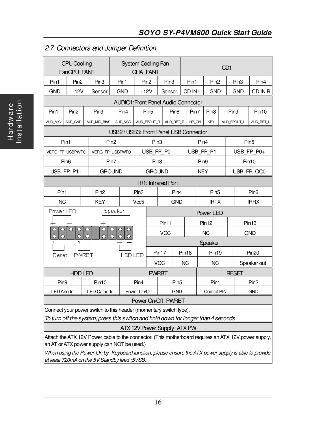
2.7 Connectors and Jumper Definition
| CPU Cooling |
|
| System Cooling Fan |
|
|
|
|
|
|
|
| CD1 |
|
| ||||||||||||||
FanCPU_FAN1 |
|
|
| CHA_FAN1 |
|
|
|
|
|
|
|
|
|
| |||||||||||||||
|
|
|
|
|
|
|
|
|
|
|
|
|
|
|
|
| |||||||||||||
Pin1 |
|
| Pin2 |
| Pin3 |
| Pin1 |
| Pin2 |
|
| Pin3 |
|
| Pin1 |
| Pin2 |
|
| Pin3 |
| Pin4 | |||||||
GND |
|
| +12V |
| Sensor |
| GND |
| +12V |
| Sensor | CD IN L |
| GND |
| GND |
| CD IN R | |||||||||||
|
|
|
|
|
|
|
| AUDIO1:Front Panel Audio Connector |
|
|
|
|
| ||||||||||||||||
Pin1 |
|
| Pin2 |
| Pin3 | Pin4 |
| Pin5 |
|
|
| Pin6 | Pin7 |
| Pin8 |
|
| Pin9 |
| Pin10 | |||||||||
AUD_MIC |
| AUD_GND | AUD_MIC_BIAS | AUD_VCC |
| AUD_FPOUT_R | AUD_RET_R | HP_ON |
| KEY |
| AUD_FPOUT_L |
| AUD_RET_L | |||||||||||||||
|
|
|
|
|
|
|
|
|
|
|
|
|
|
|
|
|
|
|
|
|
|
|
|
| |||||
|
|
|
|
|
|
| USB2 / USB3: Front Panel USB Connector |
|
|
|
|
| |||||||||||||||||
| Pin1 |
| Pin2 |
|
| Pin3 |
|
|
|
|
| Pin4 |
|
| Pin5 | ||||||||||||||
VERG_FP_USBPWR0 | VERG_FP_USBPWR0 |
| USB_FP_P0- |
|
| USB_FP_P1- |
|
| USB_FP_P0+ | ||||||||||||||||||||
| Pin6 |
| Pin7 |
|
| Pin8 |
|
|
|
|
| Pin9 |
|
| Pin10 | ||||||||||||||
USB_FP_P1+ |
| GROUND |
| GROUND |
|
|
|
|
| KEY |
|
| USB_FP_OC0 | ||||||||||||||||
|
|
|
|
|
|
|
|
|
|
| IR1: Infrared Port |
|
|
|
|
|
|
|
|
|
| ||||||||
Pin1 |
|
| Pin2 |
|
|
| Pin3 |
|
|
| Pin4 |
|
|
| Pin5 |
|
|
|
| Pin6 | |||||||||
NC |
|
| KEY |
|
| Vcc5 |
|
|
| GND |
|
|
| IRTX |
|
|
| IRRX | |||||||||||
|
|
|
|
|
|
|
|
|
|
|
|
|
|
|
|
|
|
|
|
| Power LED |
|
| ||||||
|
|
|
|
|
|
|
|
|
|
|
|
|
| Pin11 |
|
| Pin12 |
|
| Pin13 | |||||||||
|
|
|
|
|
|
|
|
|
|
|
|
|
| VCC |
|
|
| NC |
|
| GND | ||||||||
|
|
|
|
|
|
|
|
|
|
|
|
|
|
|
|
|
|
|
|
| Speaker |
|
|
|
|
| |||
|
|
|
|
|
|
|
|
|
|
|
|
| Pin17 |
| Pin18 |
|
| Pin19 |
|
|
| Pin20 | |||||||
|
|
|
|
|
|
|
|
|
|
|
|
| VCC |
|
| NC |
|
| NC |
|
| Speaker out | |||||||
|
|
| HDD LED |
|
|
|
| PWRBT |
|
|
|
|
|
|
|
|
|
| RESET |
|
| ||||||||
Pin9 |
|
| Pin10 |
|
|
| Pin4 |
|
|
| Pin5 |
|
|
| Pin1 |
|
|
|
| Pin2 | |||||||||
LED Anode |
| LED Cathode |
| Power On/Off |
|
|
| GND |
|
|
| Control PIN |
|
| GND | ||||||||||||||
Power On/Off: PWRBT
Connect your power switch to this header (momentary switch type).
To turn off the system, press this switch and hold down for longer than 4 seconds.
ATX 12V Power Supply: ATX PW
Attach the ATX 12V Power cable to the connector. (This motherboard requires an ATX 12V power supply, an AT or ATX power supply can NOT be used.)
When using the
16