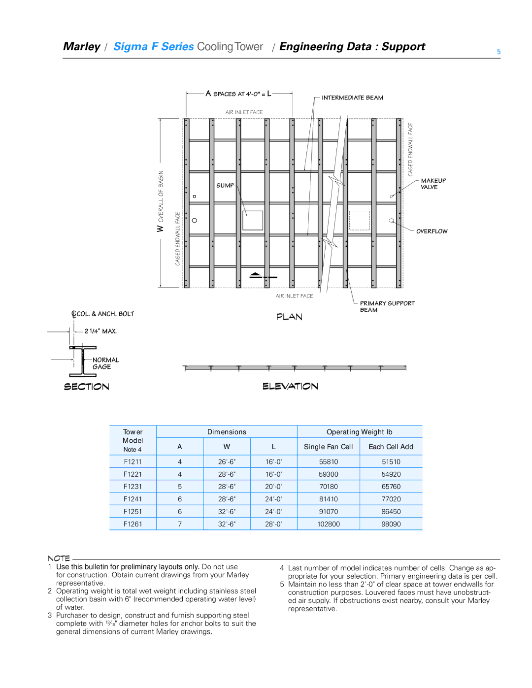
FSIG-TS-08A specifications
SPX Cooling Technologies has established itself as a leader in providing innovative cooling solutions, and the FSIG-TS-08A is a shining example of their engineering excellence. This advanced cooling system is designed for a variety of industrial and commercial applications where efficient heat exchange is crucial for optimal performance.One of the standout features of the FSIG-TS-08A is its highly efficient heat transfer capabilities. The unit utilizes a corrosion-resistant heat exchanger design that enhances thermal performance while reducing maintenance needs. This is crucial in environments where durability and longevity are paramount. The robust construction of the FSIG-TS-08A ensures that it can withstand harsh operating conditions while maintaining its efficiency over time.
Another key characteristic of the FSIG-TS-08A is its energy-saving capabilities. In an era where energy costs are continually rising, this cooling solution incorporates advanced technologies that optimize energy consumption, leading to significant cost savings. The design includes variable speed fans that automatically adjust their operation based on cooling demand, which minimizes energy usage without sacrificing performance.
Moreover, the FSIG-TS-08A is equipped with a user-friendly control system, allowing operators to easily monitor and manage the unit's performance. The integrated controls provide real-time data on system operation and efficiency, further enhancing operational reliability.
The FSIG-TS-08A also boasts a compact design, making it suitable for installation in spaces where traditional cooling solutions may not fit. Its streamlined footprint does not compromise its cooling capability, making it an ideal choice for a wide range of settings, including manufacturing plants, power generation facilities, and other industrial operations.
In terms of versatility, the FSIG-TS-08A can be customized to meet specific requirements based on the application. This adaptability empowers businesses to leverage the cooling system to meet their unique challenges effectively.
In summary, SPX Cooling Technologies' FSIG-TS-08A is a cutting-edge cooling solution combining efficiency, durability, and flexibility. With its advanced technologies, energy-saving features, and user-friendly controls, the FSIG-TS-08A is well-equipped to meet the demanding needs of today's industrial landscape. It is a testament to SPX's commitment to delivering high-quality, innovative products that help organizations improve their operational efficiency while reducing their environmental footprint.

