LC-8521
EC Council Directive 73/23/EEC and 93/68/EEC of 22 July
Chapter
About this manual
Contents
Using the Printer with MS-DOS
Using the EDS Mode
Using the Printer with Windows 3.1
Using the printer with Windows 95
Appendix a Troubleshooting
Optional Accessory
Paper Handling
Appendix F Glossary Appendix G Control Panel Operation Guide
Page
Choosing a place for the printer
Printer Setup
Unpacking the printer
Printer Setup
General guide
General guide
Removing the protective materials
Installing the platen knob
Installing the platen knob
Opening the front cover
Installing the ribbon cassette
Removing the ribbon cassette
Removing the ribbon cassette
Printer Setup
Connecting to a power outlet and turning power on and off
Connecting to a power outlet and turning power on and off
Loading fanfold paper
Loading fanfold paper
Pin tractor Sheet guide
Loading fanfold paper
Printing on fanfold paper
Parking fanfold paper
Using the tear-off function
Parking fanfold paper
Unparking fanfold paper
Connecting to your computer with a parallel cable
Page
Connecting to your computer with a serial cable
Connecting to your computer with a serial cable
Control Panel Operations
Switching between on-line and off-line
Control Panel Operations
Selecting a font
Entering the Font Lock Mode
Lit Indicator Font
Selecting a font
Entering the Pitch Lock Mode
Setting the character pitch
Lit Indicators Meaning
Micro feed
Line feed
Paper eject cut-sheet paper
Form feed fanfold paper
Selecting the Quiet Print Mode
Setting the top of form position
Tear-off function fanfold paper
Changing the auto load position
Changing the auto load position
Clearing the printer’s buffer
Saving a macro
Initializing the printer
Entering the Multi-part Mode
Initializing the printer
Using the EDS Mode
Using the EDS Mode
About EDS Mode settings
Entering the EDS Mode
Selecting a bank
Lit Indicator Selected Bank
Selecting a bank
EDS Modes Settings
Selecting a switch
Changing a switch setting
Printing the current switch settings
EDS-1 Settings
Switch 4 Auto LF with CR
Switch 1 Graphics Direction
Switch 2 Auto Tear-off
Switch 3 Line Spacing
Print Mode
Switches 1, 2 Print Mode
Switches 3, 4, 5 Print Pitch
Switch 6 Quiet
Length
Switches 1, 2, 3, 4 Page Length
Switch 5 Eject direction for cut sheet
Switch 6 Skew sensor for cut sheet
SW1 SW2 SW3 SW4 SW5 SW6
Code
IBM PC
Name Country Remarks
Country Remarks
Character Set
International
Switch 1 Data Length
EDS-2 Settings
EDS-2 Settings
Switches 1, 2, 3, 4, 5, 6 LQ Font Selection
Switch 5, 6 Not used
Switch 2 Parity Check
Switch 3 Parity
Switch 4 Protocol
Baud Rate
Switch 1, 2, 3 Baud Rate
Switch 1, 2, 3, 4, 5, 6 Paper Control
Switch Setting Meaning
Setting up for printing with Microsoft Windows
Using the Printer with Windows
Using the Printer with Windows
Setting up for printing with Microsoft Windows 3.1
Getting ready to print
Printing a document
Printing a document
Installing TrueType fonts
Selecting fonts in Windows applications
Setting up the printer in Windows
Have Disk button
Page
Preparing to print
Preparing to print
Using the printer with Windows
Printing a document
Installing TrueType fonts
Installing TrueType fonts
Setting up for printing with MS-DOS
Using the Printer with MS-DOS
Using the Printer with MS-DOS
Fanfold Paper
Paper Handling
Selecting paper types
Cut-Sheet Paper
Paper Handling
Adjusting for paper thickness
Envelope
Paper Type
Automatic fanfold feeding
Thickness
Manual sheet feeding
Adjust the paper guide to the position you want
Clearing paper jams
Serial-to-Parallel Converter SPC-8K
Optional Accessory
Connecting the Interface Converter
Setting the converter’s DIP switches
Setting the converter’s DIP switches
Switc Function
Protocol
Data Length Switch
DOS/Windows Setting
Parity
Push Tractor Unit CT-15HA
Push Tractor Unit CT-15HA
Removing the push tractor unit from the back of the printer
Installing the push tractor unit
Long test
Appendix a Troubleshooting
Troubleshooting
Short test
Hexadecimal dump
Adjusting the dot alignment
Hexadecimal dump
DOT Adjustment Setting
Troubleshooting guide
Troubleshooting guide
Problem Possible Cause
Interface cable is
Printed on Return is enabled
Printer case is hot Printer’s air vents are
Left margin moves to Paper is not loaded
Print head Dealer for repair
To check the Driver Setup
Checking system software settings in Windows
Checking system software settings in Windows
To check the default printer selection
To check the application printer selection
Checking system software settings in MS-DOS
To check the port
Appendix B Specifications
Checking system software settings in MS-DOS
Specifications
Pin
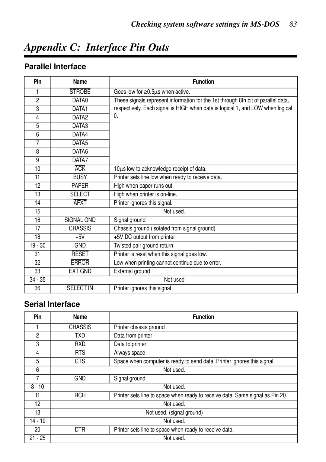
Appendix C Interface Pin Outs
Parallel Interface
Serial Interface
Character Sets
Appendix D Character Sets
Standard Italic Character Set International Character Set
IBM Character Set #2 Code Page #437 IBM-PC Character Set #1
Code Page #861 Icelandic
IBM Special Character Set
Code Page #860 Portuguese
Code Page #850 Multi-lingual
Code Page #3840 IBM-Russian
Code Page #863 Canadian French
Code Page #866 Russian
Code Page #865 Nordic
Code Page #3845 Hungarian
Code Page #3841 Gost-Russian
Code Page #3844
Code Page #3843 Polish
Code Page #852 Latin-2
Code Page #3846 Turkish
Code Page #3848 Brazil-ABICOMP
Code Page #3847 Brazil-ABNT
Code Page #851 Greek
Code Page #1001 Arabic Code Page #737 Greek
Code Page #772 Lithuanian
Code Page #869 Greek
Code Page #2001 Lithuanian-KBL
Code Page #928 Greek
Code Page #3011 Latvian1
Code Page #774 Lithuanian
Code Page #3002 Estonian2
Code Page #3001 Estonian1
Code Page #3041 Maltese
Code Page #3012 Latvian2
Code Page #3031 Hebrew
Code Page #3021 Bulgarian
Code Page #3863
Code Page #3850 Standard KU
Code Page #3861 Microwiz KU
Code Page #3860 Rajvitee KU
Code Page #3865 Newsic TIS
Code Page #3864 Popular TIS
Printer Control Codes
Font and Character Set Control Commands
Description Mode Ascii Code
Appendix E Printer Control Codes
Top/Bottom Margin and Vertical Tab Commands
Print Pitch Control Commands
Bit Image Graphic Commands
Special Print Mode Commands
Form Feed and Related Commands
Line Spacing Commands
Download Character Commands
Other Commands
Horizontal Print Position Control Commands
NEC Commands
Appendix F Glossary
Appendix G Control Panel Operation Guide
Maltese 93, 94
MS-DOS
Page
Page
Customer service information