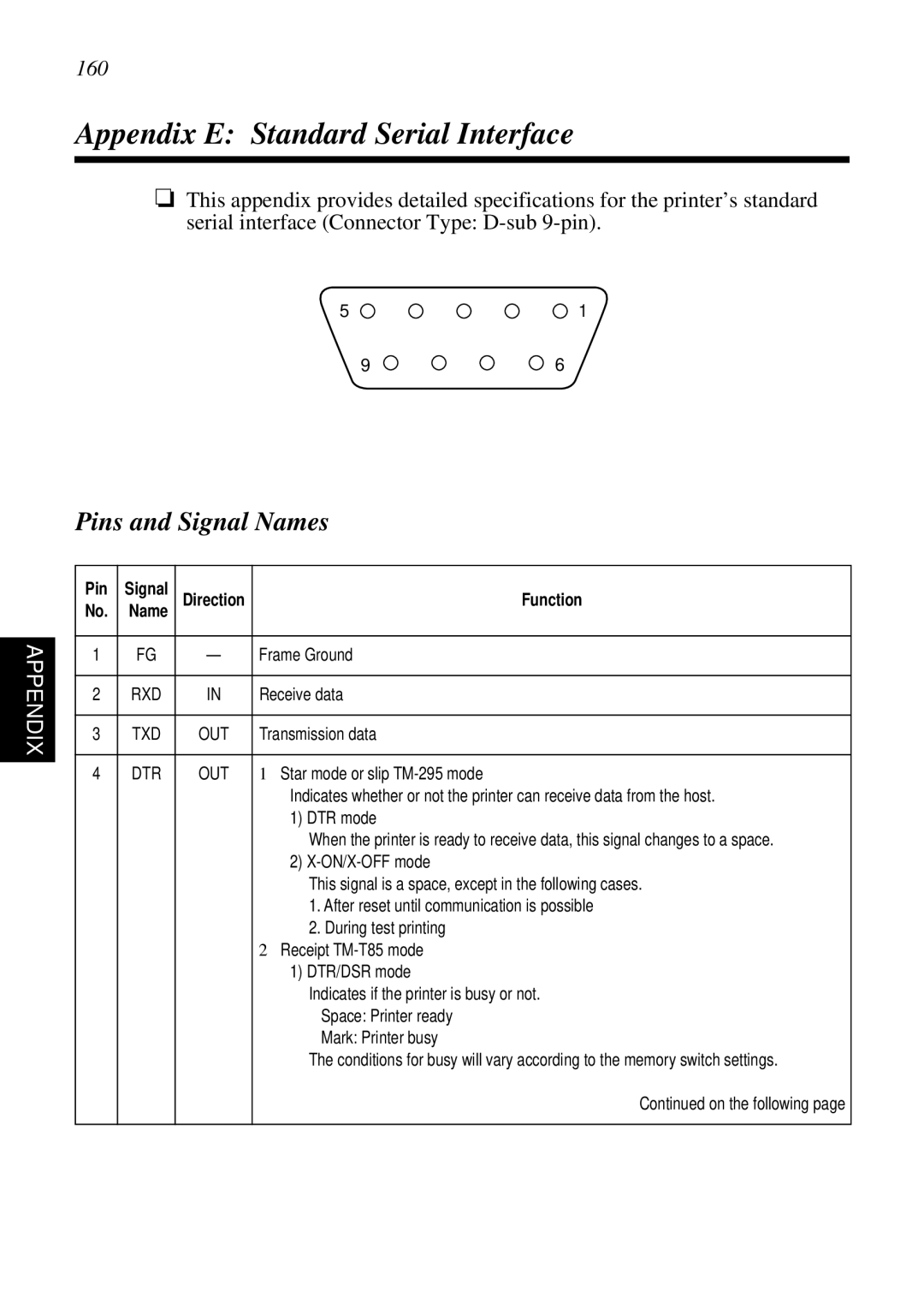
SCP700 specifications
The Star Micronics SCP700 series is a cutting-edge solution designed to meet the needs of modern retail and hospitality environments. Known for its exceptional performance and reliability, this compact thermal printer is widely esteemed for its versatility and ease of use. The SCP700 is particularly popular among various sectors, including restaurants, cafes, and retail shops, due to its key features and advanced technologies.One of the standout characteristics of the SCP700 is its compact design. Measuring only a few inches in height, it easily fits into limited counter spaces, making it ideal for businesses where space is at a premium. Despite its small footprint, the printer offers a range of functionalities, providing users with a powerful tool for printing receipts, tickets, and various types of documentation quickly and efficiently.
The SCP700 series leverages advanced thermal printing technology that ensures high-quality prints with crisp text and graphics. With a print speed of up to 200 millimeters per second, businesses can ensure rapid transaction processing, enhancing customer satisfaction. Furthermore, the printer supports multiple paper widths, giving users the flexibility to choose the best option for their needs.
Connectivity is another strong suit of the SCP700 series. The printer offers various options, including USB, Ethernet, and Bluetooth capabilities, allowing seamless integration with different point-of-sale systems. This wide range of connectivity options ensures that the printer can easily adapt to existing setups while also keeping pace with technological advancements.
Reliability is crucial in demanding business environments, and the SCP700 delivers on this front. Engineered for longevity, the printer boasts a durable construction that can withstand the day-to-day rigors of high-volume printing. Its easy paper loading mechanism simplifies maintenance, while the high-capacity paper roll reduces the frequency of replacements, allowing staff to focus on service rather than printer upkeep.
In addition to its robust hardware, the SCP700 also features user-friendly software compatibility. It supports various operating systems, ranging from Windows to iOS and Android, making it versatile for businesses utilizing different platforms.
In conclusion, the Star Micronics SCP700 series is a superb choice for businesses looking for an efficient and dependable thermal printing solution. Its compact design, high-speed performance, robust connectivity options, and overall reliability make it an invaluable asset in today’s fast-paced commercial environment. The SCP700 stands out as a powerful tool that enhances productivity and contributes to a superior customer experience.

