THEORY OF OPERATION
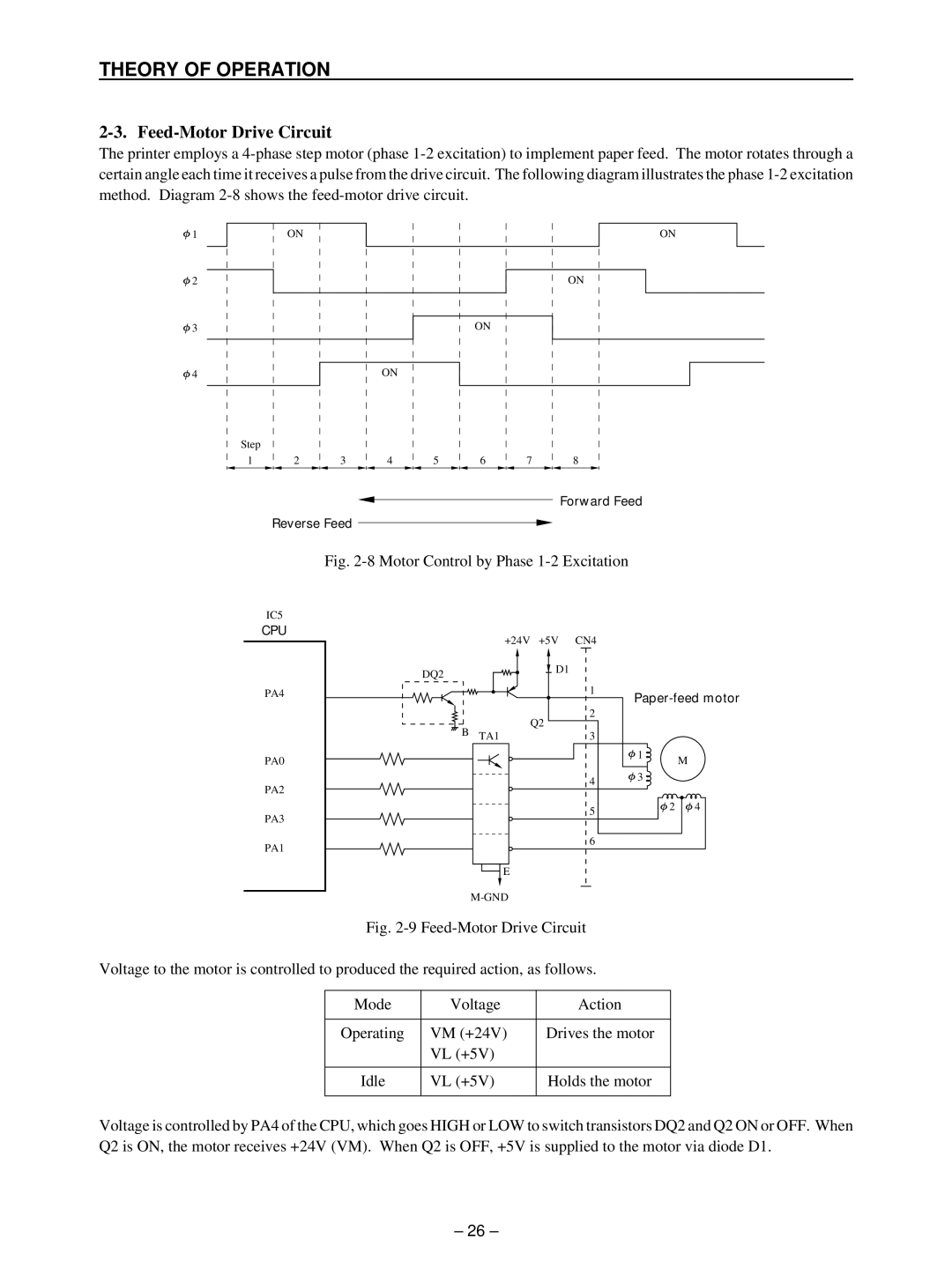
2-3. Feed-Motor Drive Circuit
The printer employs a
![]() 1
1
ON
ON
![]() 2
2
ON
![]() 3
3
ON
![]() 4
4
ON
Step
1 |
| 2 |
| 3 |
| 4 |
| 5 |
| 6 |
| 7 |
| 8 |
Forward Feed
Reverse Feed
Fig. 2-8 Motor Control by Phase 1-2 Excitation
IC5
CPU
PA4
| +24V | +5V CN4 | |
DQ2 |
| D1 | |
|
| ||
|
| 1 | |
|
| 2 | |
B |
| Q2 | |
TA1 | 3 | ||
|
PA0
PA2
4 |
1
![]() 3
3
M
PA3
PA1
5 |
6 |
E |
2 | 4 |
|
|
Fig. 2-9 Feed-Motor Drive Circuit
Voltage to the motor is controlled to produced the required action, as follows.
Mode | Voltage | Action |
|
|
|
Operating | VM (+24V) | Drives the motor |
| VL (+5V) |
|
|
|
|
Idle | VL (+5V) | Holds the motor |
|
|
|
Voltage is controlled by PA4 of the CPU, which goes HIGH or LOW to switch transistors DQ2 and Q2 ON or OFF. When Q2 is ON, the motor receives +24V (VM). When Q2 is OFF, +5V is supplied to the motor via diode D1.
– 26 –