Star Micronics TSP400 technical manual 2-5. +5V Line Voltage Detector Circuit, Theory Of Operation

Models: TSP400

1 80
Download 80 pages 15.17 Kb
Page 32
Image 32
2-5. +5V Line Voltage Detector Circuit

THEORY OF OPERATION

2-5. +5V Line Voltage Detector Circuit

The voltage-detection IC (IC4 in Fig. 2-10) detects momentary drops or unstable levels in the +5V line voltage. IC4 operation is illustrated by the equivalence circuit shown below.

R1

R2

1.25V

VCC

Manual background 1

SA typ

+

Manual background 3

GND

Manual backgroundManual background

Manual background 4

Cd

5

Manual backgroundManual background OUT

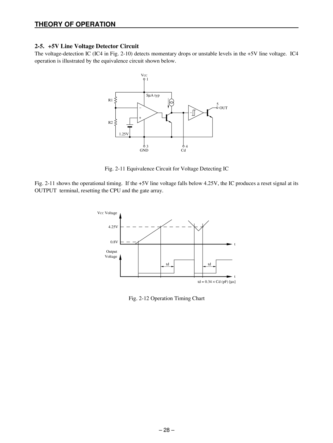
Fig. 2-11 Equivalence Circuit for Voltage Detecting IC

Fig. 2-11 shows the operational timing. If the +5V line voltage falls below 4.25V, the IC produces a reset signal at its OUTPUT terminal, resetting the CPU and the gate array.

VCC Voltage


4.25V


0.8V

t


Output


Voltage


td

td


t


td = 0.34 × Cd (pF) [s]

Fig. 2-12 Operation Timing Chart

– 28 –

Page 32
Image 32
Star Micronics TSP400 technical manual 2-5. +5V Line Voltage Detector Circuit, Theory Of Operation