Manuals
/
Star Micronics
/
Computer Equipment
/
Printer
Star Micronics
TSP400
technical manual
Lubrication Points
Models:
TSP400
1
51
80
80
Download
80 pages
15.17 Kb
48
49
50
51
52
53
54
55
Specification
Parts list
Block Diagram
Maintenance
Internal Configuration TSP412D
Power-On Reset Circuit
Feed Motor Assembly
Print-Density Adjustment
DIP-Switch Settings
Cleaning
Page 51
Image 51
MAINTENANCE AND LUBRICATION
1
C
D
8
B
7
6
1
6
C
A
9
B
A
D
9
4
2
3
5
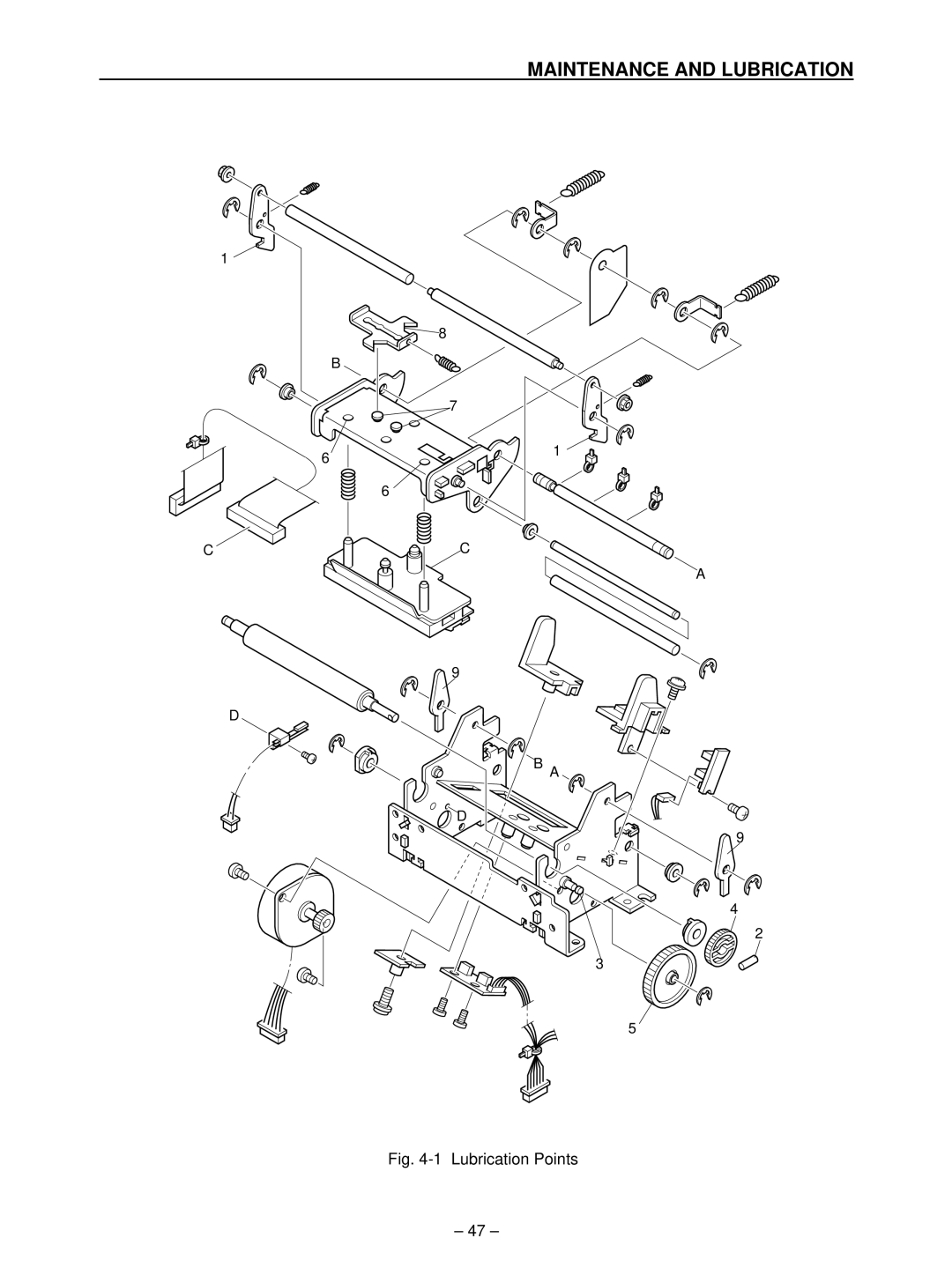
Fig.
4-1
Lubrication Points
– 47 –
Page 50
Page 52
Page 51
Image 51
Page 50
Page 52
Contents
TSP400 Series
Page
Introduction
Page
Chapter Specifications and Operation
Specifications and Operation
OCR-B
General Specifications
Internal Configuration TSP412D
External Appearance and Internal Configuration
DIP-Switch Settings
Status of printer power
Baud
Print-Density Adjustment
Sensor Adjustment
Specifications and Operation
Setting Memory Switches from the Control Panel
HEX Dump
Test Print
Page/Line Mode Switch
Exposing the Peripheral Unit Connector
Changing the Interface Board
Specifications and Operation
Chapter Theory of Operation
Theory of Operation
24V
Block Diagram
Control Panel
Interface
Main and Interface PCBs
2. RS422A interface
Parallel Interface PCB Main PCB
Editing
Editing and Printing
Timing Chart
Feed-Motor Drive Circuit
Motor Control by Phase 1-2 Excitation
Power-On Reset Circuit
11 Equivalence Circuit for Voltage Detecting IC
+5V Line Voltage Detector Circuit
Printer Mechanism
Thermal Head
Paper-Feed Mechanism
15 Paper-Out Detector
Detectors
19 Head-Up Detector
Page
Chapter Parts Replacement and Related Adjustments
Parts Replacement
TSP412D
Upper Casing Unit
Control-Panel Board
Printer Mechanism
Main PCB, Interface PCB
Fuse
Power Unit
Printhead unit
Feed Motor Assembly
Label sensor
Detectors
Parts Replacement
Chapter Maintenance and Lubrication
Maintenance and Lubrication
Maintenance
Cleaning
Checks
Lubrication Points
Lubrication
Lubricants
Application Method
Lubrication Points
Maintenance and Lubrication
Chapter Parts List
Disassembly Drawing
Printer Assembly
TSP442D
Printer Assembly
Parts List
Screw TAT
Printer Mechanism Assembly
Oiless Bushing F4X7X3
Printer Mechanism
RS-232C Interface Type
Connector Wiring Diagram
RS422A I/F Board Control Board
Parallel Interface Type
Main Logic Board
Circuit Diagram
Side a
Side D
Side C
Main Logic Board
Chip Resistor 20 K-OHM 1/10W
CN8
RS232C Interface
RS232C Interface Board
RS422A Interface
RS422A Interface Board
CentronicsInterface
Centronics Interface Board
Control Panel Board
Control Panel Board
Transmissive Sensor
Paper-Out Detector Board
Label Sensor Board
Paper-Out Detector
Page
Distributed by
Top
Page
Image
Contents