of how they impact the Model 233’s operation can lead to many interesting and powerful uses.
Talkback to Intercom Functions
The last two switches in switch assembly SW2 are used to configure the talkback to intercom functions.
Talkback 1 to Intercom Function Mode
Switch
Figure 21. Talkback 1 to intercom pin 2 settings
Two modes are available:
•Disabled: In this mode the talkback 1 button will not allow talkback audio to be sent to pin 2 of the intercom interface.
•Talkback 1 to intercom interface pin 2: In this mode the talkback 1 button will control the routing of talkback audio to pin 2 of the intercom interface. Pin 2 is channel 1 of an RTS intercom system.
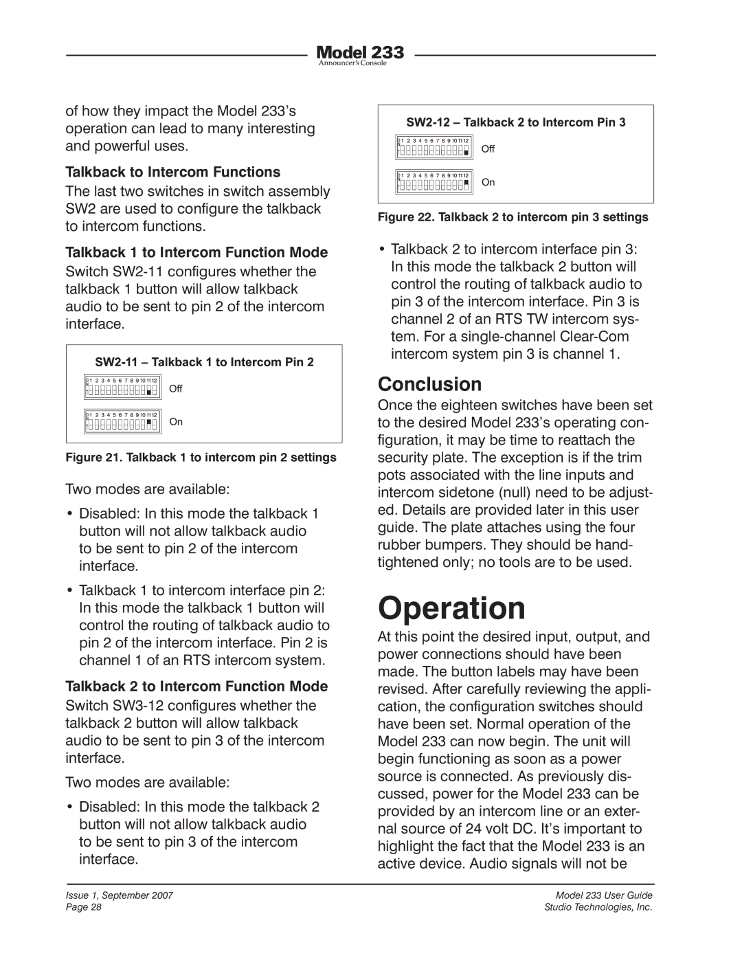
Talkback 2 to Intercom Function Mode
Switch
Two modes are available:
•Disabled: In this mode the talkback 2 button will not allow talkback audio to be sent to pin 3 of the intercom interface.
Figure 22. Talkback 2 to intercom pin 3 settings
•Talkback 2 to intercom interface pin 3: In this mode the talkback 2 button will control the routing of talkback audio to pin 3 of the intercom interface. Pin 3 is channel 2 of an RTS TW intercom sys- tem. For a
Conclusion
Once the eighteen switches have been set to the desired Model 233’s operating con- figuration, it may be time to reattach the security plate. The exception is if the trim pots associated with the line inputs and intercom sidetone (null) need to be adjust- ed. Details are provided later in this user guide. The plate attaches using the four rubber bumpers. They should be hand- tightened only; no tools are to be used.
Operation
At this point the desired input, output, and power connections should have been made. The button labels may have been revised. After carefully reviewing the appli- cation, the configuration switches should have been set. Normal operation of the Model 233 can now begin. The unit will begin functioning as soon as a power source is connected. As previously dis- cussed, power for the Model 233 can be provided by an intercom line or an exter- nal source of 24 volt DC. It’s important to highlight the fact that the Model 233 is an active device. Audio signals will not be
Issue 1, September 2007 | Model 233 User Guide |
Page 28 | Studio Technologies, Inc. |