one of the talkback outputs is active. The level control on the far right adjusts the
Astute readers will realize that sidetone au- dio can also be provided from the intercom cue sources during Model 233 talkback to intercom activity. This “passive” sidetone is created in the intercom interface’s ana- log talk/listen hybrid sidetone (null) circuit. Trim pots allow the intercom sidetone level to be adjusted over a limited range. To get maximum performance when either or both intercom channels are used as a cue source one simple calibration process may need to be performed. This involves ad- justing the sidetone (null) trim pots to their fully counterclockwise positions, providing minimum sidetone level. This will reduce the level “build up” that would occur when both the main and the intercom sidetone audio signals are sent to the headphone output. The goal is for the sidetone level to remain as constant as possible, no matter what
Let’s begin with an application that has a stereo cue source connected to the line inputs. The cue source selection switches are configured to create a stereo head- phone output with line input 1 assigned
to the left channel and line input 2 assigned to the right channel. Begin the trim pot adjustment process by moving the user level controls (located on the front panel) to their detent (50% of rotation) positions. Then, with the stereo cue source provid- ing signal at its normal level, adjust the trim pots to provide a comfortable level
Advanced
Operation
Adjusting the Line Input Trim Pots
As has been previously mentioned, associ- ated with the two line inputs are trim pots that allow the input levels to be adjusted. The two trim pots are accessible by way of round openings in the bottom of the Model 233’s enclosure. By adjusting these trim pots, signals with a nominal signal level of
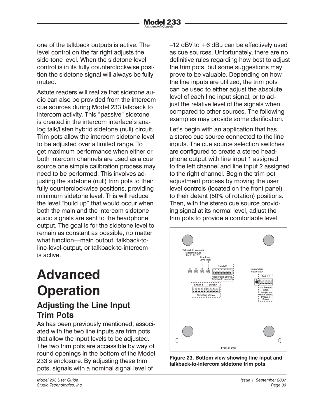
Figure 23.
23. Bottom
 view showing line input and
 talkback-to-intercom sidetone trim pots
Model 233 User Guide | Issue 1, September 2007 |
Studio Technologies, Inc. | Page 33 |