It is visible by observing the bottom of the Model 233’s enclosure when the security plate has been removed. Technically, this red LED lights whenever the compressor circuitry is controlling the dynamic range of the signal coming from the microphone preamplifier. The threshold is set to be 2 dB above the Model 233’s nominal internal operating level. So a good “rule of thumb” is to adjust the gain of the microphone preamplifier so that the compressor active LED lights (“flashes”) when the connected microphone is sending signal peaks. During normal operation the LED should not remain fully lit when typical audio sig- nals are present on the mic input.
It’s important to remember that the com- pressor active LED is used to assist in set- ting the mic preamplifier gain to the optimal value. It doesn’t necessarily indicate that the main output’s signal is being compressed. Unless specifically configured to perform otherwise, the output of the compressor is only used for the talkback output functions.
It’s expected that the 20 and 60 dB gain settings will not often be used. But there are always exceptions and that’s why they were included. It’s possible that with a very “hot” microphone, such as a phantom- powered
Note that if no gain switch is set to its ac- tive (on) position the Model 233’s preampli- fier will operate at unity (0 dB) gain. In this mode the preamplifier will remain stable, but is intended only for use during factory testing. A valid exception would be where
a
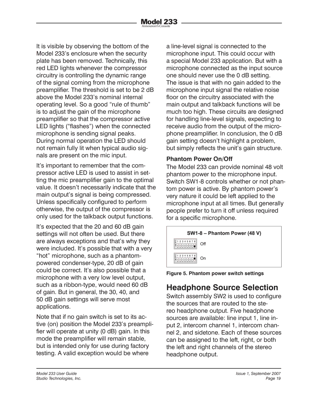
Phantom Power On/Off
The Model 233 can provide nominal 48 volt phantom power to the microphone input. Switch
Figure 5. Phantom power switch settings
Headphone Source Selection
Switch assembly SW2 is used to configure the sources that are routed to the ste- reo headphone output. Five headphone sources are available: line input 1, line in- put 2, intercom channel 1, intercom chan- nel 2, and sidetone. Each of these sources can be assigned to the left, right, or both the left and right channels of the stereo headphone output.
Model 233 User Guide | Issue 1, September 2007 |
Studio Technologies, Inc. | Page 19 |