O P T I O N A L
C O M P O N E N T S
Optional installa- tion components are available through your
S U B - Z E RO MODELS 315I A N D 315IP I N S TA L L AT I O N
MODEL 315IP D R A I N P U M P |
| ||
1) | Place the ice maker in front of the installa- | D R A I N P U M P K I T | |
| tion opening. Adjust leveling legs to the | This ice maker can be ordered with a drain | |
| approximate height. | ||
| pump (Model 315IP) or without (Model 315I). | ||
2) | Remove the control knob, control panel and | ||
Models without a pump drain their water by | |||
| control access panel. | gravity. However, gravity drain models may | |
3) | Route the water inlet line (1/4" OD copper | be converted to pump models through the | |
| tube) from the wall through the ice maker | installation of a drain pump kit. | |
|
| ||
| to the front. | The parts required for this conversion are | |
4) | Locate the coil of 3/8" ID plastic drain tubing | available through your | |
| secured to the back of the unit. | can also visit the Locator section of our website, | |
| subzero.com, to obtain information on the local | ||
5) | Route the plastic drain tube from the back | ||
parts distributor and/or dealer in your market. | |||
| of the unit to the drain connection point. | ||
| Detailed installation instructions are included | ||
|
| ||
IMPORTANT NOTE: Often an air gap is | with the kit. | ||
required by local codes between the ice maker | Drain pump kit (#A36892020) | ||
|
| ||
drain tube and the drain receptacle. Refer to | Drain pump (#12250321) | |
the illustration below. | ||
|
6)If the electrical outlet for the ice maker is
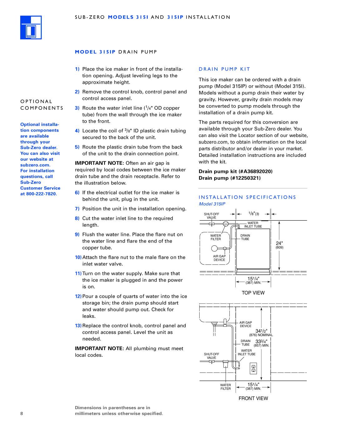
behind the unit, plug in the unit. | I N S TA L L AT I O N S P E C I F I C AT I O N S | |
Model 315IP | ||
|
8
7)Position the unit in the installation opening.
8)Cut the water inlet line to the required length.
9)Flush the water line. Place the flare nut on the water line and flare the end of the copper tube.
10)Attach the flare nut to the male flare on the inlet water valve.
11)Turn on the water supply. Make sure that the ice maker is plugged in and the power is on.
12)Pour a couple of quarts of water into the ice storage bin; the drain pump should start and water should pump out. Check for leaks.
13)Replace the control knob, control panel and control access panel. Level the unit as needed.
IMPORTANT NOTE: All plumbing must meet local codes.
Dimensions in parentheses are in millimeters unless otherwise specified.
1/8"(3) | |
VALVE |
|
| WATER |
| INLET TUBE |
WATER | DRAIN |
FILTER | TUBE |
24"
(609)
AIR GAP
DEVICE
151/4"
![]() (387) MIN.
(387) MIN. ![]()
TOP VIEW
![]()
![]() AIR GAP
AIR GAP
DEVICE
341/2"
(876) NOMINAL
|
|
|
|
|
|
|
|
| DRAIN 333/4" |
|
|
|
|
|
|
|
|
| TUBE (857) MIN. |
|
|
|
|
|
|
|
|
| WATER |
| INLET TUBE | ||||||||
VALVE |
|
|
| ||||||
|
|
|
|
|
|
|
|
|
|
WATER | 151/4" |
FILTER | (387) MIN. |
FRONT VIEW