S U B - Z E RO MODELS 315I A N D 315IP
INSTALLATION
D O O R PA N E L I N S TA L L AT I O N
You should be sure of the door panel size and placement before proceeding with the installa- tion. If you have questions, contact your
For door handle hardware, a
M O D E L S 3 1 5 I A N D 3 1 5 I P
Door Panel Width – 1/8" (3) reveal |
| 15" (381) | |
Door Panel Height – 1/8" (3) reveal |
|
| |
4" (102) toe space |
| 30 | 3/8" (772) |
Door Panel Thickness |
| 5/8" | (16) min |
Door Panel Weight | 15 lbs (6.8 kg) max | ||
|
|
|
|
Dimensions may vary + 1/8" (3).
I N S TA L L AT I O N
Remove the handle side bracket attached to the front of the door and set aside.
Place the door panel lying face down on a protected surface to ensure the front is not scratched or damaged.
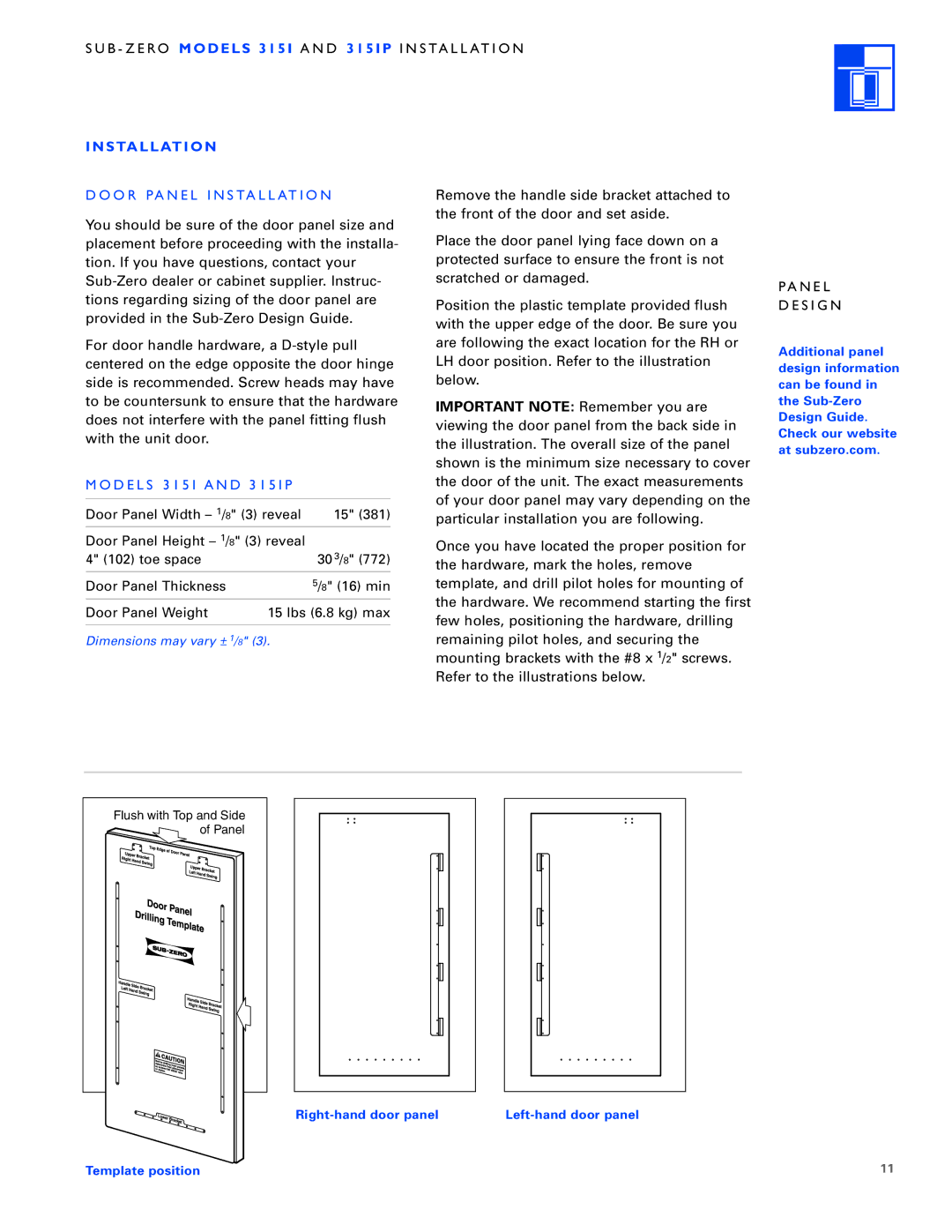
Position the plastic template provided flush with the upper edge of the door. Be sure you are following the exact location for the RH or LH door position. Refer to the illustration below.
IMPORTANT NOTE: Remember you are viewing the door panel from the back side in the illustration. The overall size of the panel shown is the minimum size necessary to cover the door of the unit. The exact measurements of your door panel may vary depending on the particular installation you are following.
Once you have located the proper position for the hardware, mark the holes, remove template, and drill pilot holes for mounting of the hardware. We recommend starting the first few holes, positioning the hardware, drilling remaining pilot holes, and securing the mounting brackets with the #8 x 1/2" screws. Refer to the illustrations below.
PA N E L
D E S I G N
Additional panel design information can be found in the
Flush with Top and Side |
of Panel |
Template position | 11 |