v i i . o p e r at i n g i n s t r u c t i o n s
R.BACK POSITIONING PLATE HEIGHT ADJUSTMENT
1.Open the exterior back panel fabric sections on the outside to expose the back growth slots and adjustment screws.
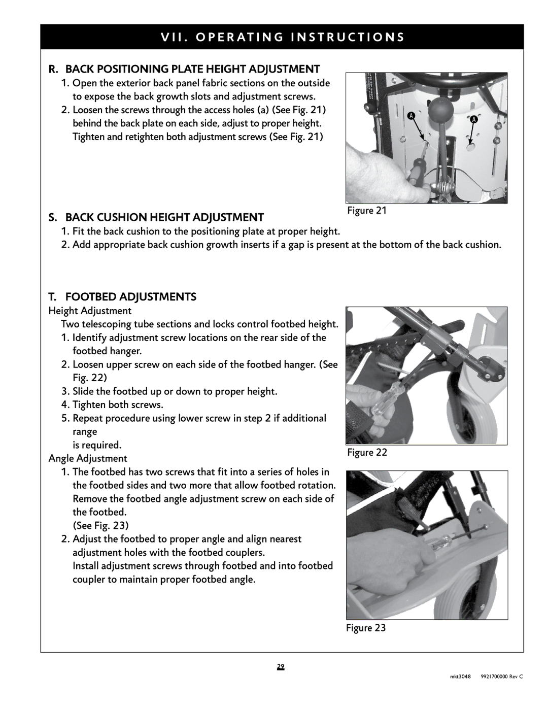
2.Loosen the screws through the access holes (a) (See Fig. 21) behind the back plate on each side, adjust to proper height. Tighten and retighten both adjustment screws (See Fig. 21)
S.BACK CUSHION HEIGHT ADJUSTMENT
Figure 21
1.Fit the back cushion to the positioning plate at proper height.
2.Add appropriate back cushion growth inserts if a gap is present at the bottom of the back cushion.
T. FOOTBED ADJUSTMENTS
Height Adjustment |
|
|
|
| |
|
|
|
| ||
Two telescoping tube sections and locks control footbed height. |
|
|
|
| |
1. Identify adjustment screw locations on the rear side of the |
|
|
|
| |
| footbed hanger. |
|
|
|
|
2. | Loosen upper screw on each side of the footbed hanger. (See |
|
|
|
|
| Fig. 22) |
|
|
|
|
3. | Slide the footbed up or down to proper height. |
|
|
|
|
4. | Tighten both screws. |
|
|
|
|
5. | Repeat procedure using lower screw in step 2 if additional |
|
|
|
|
| range |
|
|
|
|
| is required. |
|
|
|
|
|
|
|
|
| |
|
| Figure 22 |
|
| |
Angle Adjustment |
|
|
| ||
|
|
|
| ||
|
|
|
| ||
1.The footbed has two screws that fit into a series of holes in the footbed sides and two more that allow footbed rotation. Remove the footbed angle adjustment screw on each side of the footbed.
(See Fig. 23)
2.Adjust the footbed to proper angle and align nearest adjustment holes with the footbed couplers.
Install adjustment screws through footbed and into footbed coupler to maintain proper footbed angle.
Figure 23
29
mkt3048 9921700000 Rev C
