Chapter 2: Installation
DIMM Module Population Configuration
1. For motherboards prior to PCB Rev. 2.0
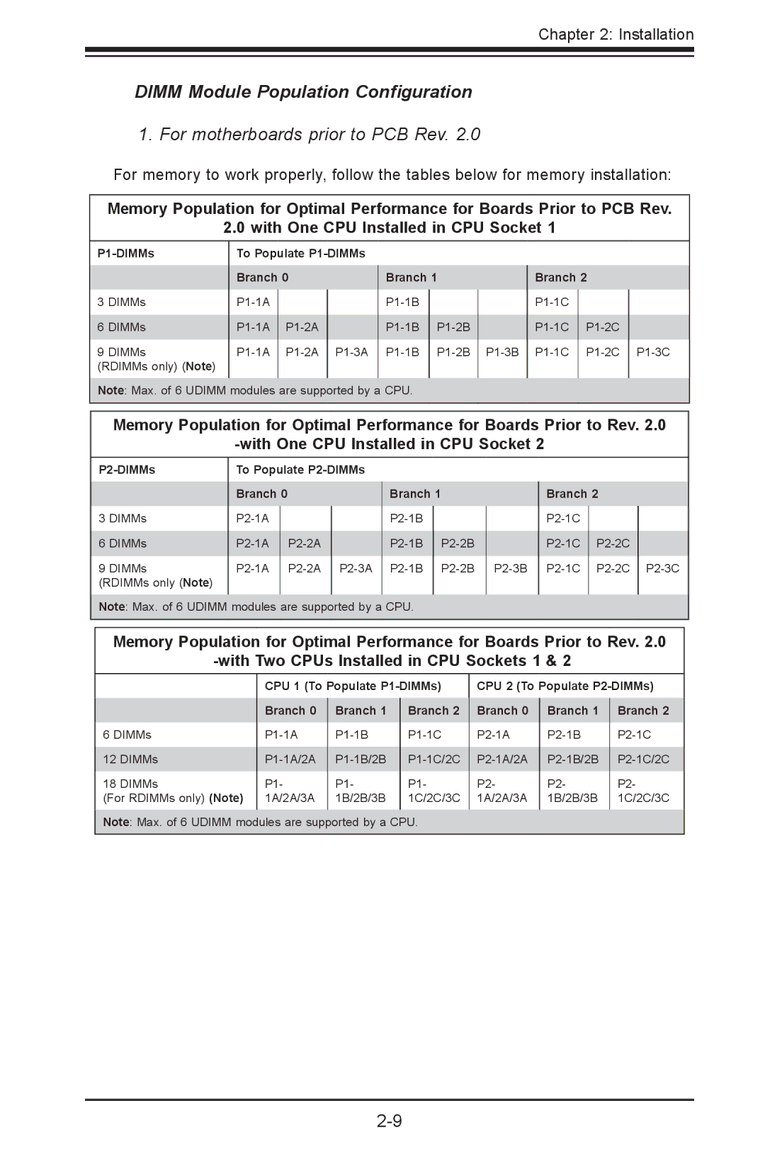
For memory to work properly, follow the tables below for memory installation:
Memory Population for Optimal Performance for Boards Prior to PCB Rev.
2.0 with One CPU Installed in CPU Socket 1
| To Populate |
|
|
|
|
|
| ||
| Branch 0 |
| Branch 1 |
| Branch 2 |
| |||
|
|
|
| ||||||
3 DIMMs |
|
|
|
|
|
| |||
|
|
|
|
|
| ||||
6 DIMMs |
|
|
| ||||||
9 DIMMs | |||||||||
(RDIMMs only) (Note) |
|
|
|
|
|
|
|
|
|
|
|
|
|
|
|
|
|
|
|
Note: Max. of 6 UDIMM modules are supported by a CPU.
Memory Population for Optimal Performance for Boards Prior to Rev. 2.0
| To Populate |
|
| |||
| Branch 0 |
|
| Branch 1 | ||
|
|
| ||||
3 DIMMs |
|
|
|
| ||
|
|
|
| |||
6 DIMMs |
|
| ||||
9 DIMMs |
| |||||
(RDIMMs only (Note) |
|
|
|
|
|
|
|
|
|
|
|
|
|
Note: Max. of 6 UDIMM modules are supported by a CPU.
| Branch 2 |
| |
|
|
| |
|
|
| |
|
| ||
|
|
|
|
Memory Population for Optimal Performance for Boards Prior to Rev. 2.0
| CPU 1 (To Populate | CPU 2 (To Populate | ||||
| Branch 0 | Branch 1 | Branch 2 | Branch 0 | Branch 1 | Branch 2 |
6 DIMMs | ||||||
12 DIMMs | ||||||
18 DIMMs | P1- | P1- | P1- | P2- | P2- | P2- |
(For RDIMMs only) (Note) | 1A/2A/3A | 1B/2B/3B | 1C/2C/3C | 1A/2A/3A | 1B/2B/3B | 1C/2C/3C |
|
|
|
|
|
|
|
Note: Max. of 6 UDIMM modules are supported by a CPU.
