![]()
![]()
![]()
![]()
![]()
![]()
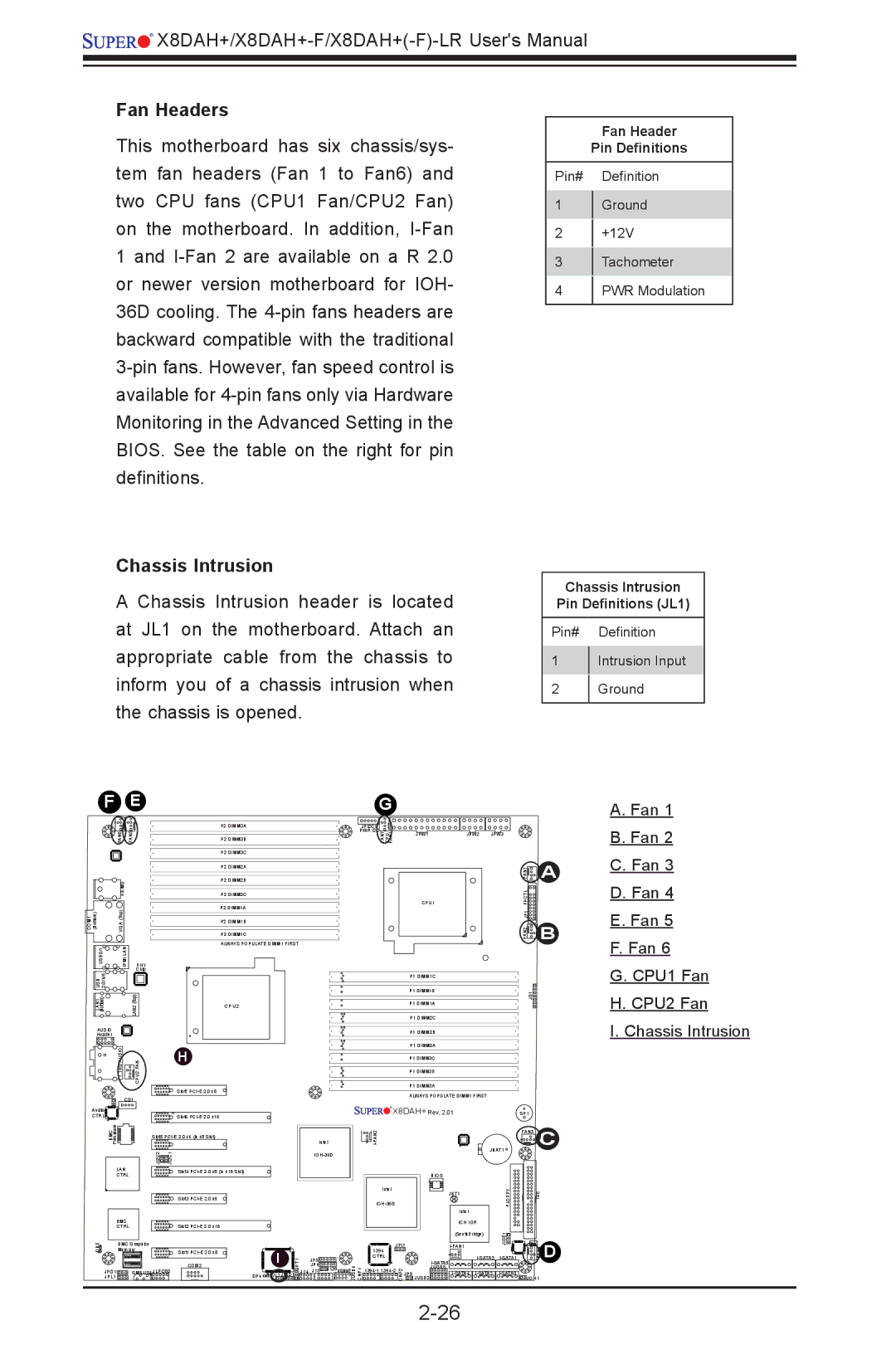
Fan Headers
This motherboard has six chassis/sys- tem fan headers (Fan 1 to Fan6) and two CPU fans (CPU1 Fan/CPU2 Fan) on the motherboard. In addition,
Chassis Intrusion
A Chassis Intrusion header is located at JL1 on the motherboard. Attach an appropriate cable from the chassis to inform you of a chassis intrusion when the chassis is opened.
Fan Header
Pin Definitions
Pin# Definition
1Ground
2+12V
3Tachometer
4PWR Modulation
Chassis Intrusion
Pin Definitions (JL1)
Pin# Definition
1Intrusion Input
2Ground
F | E |
| G |
|
|
|
|
| P2 DIMM3A | JPI2C1 |
|
|
|
FAN6 | FAN5 | P2 DIMM3B | PWR I2C |
|
|
|
FAN7 CPU FAN1 | JPW1 | JPW2 | JPW3 |
P2 DIMM3C
A. Fan 1 B. Fan 2
| KB/MS |
|
COM1 (Bottom) | VGA (Top) |
|
USB0/1 | IPMI LAN | PHY |
USB 2/3/4/5 |
| Chip |
| LAN2(Top) | |
(Bottom) |
| |
LAN1 |
|
|
AUDIO |
|
|
Header |
|
|
| 7.1HD AUDIO | CPU2 FAN |
| CD1 | |
Audio |
|
|
CTRL |
|
|
P2 DIMM2A
P2 DIMM2B
P2 DIMM2C
P2 DIMM1A
P2 DIMM1B
P2 DIMM1C
ALWAYS POPULATE DIMM1 FIRST
CPU2
H
Slot7
Slot6
CPU1 |
P1 DIMM1C
P1 DIMM1B
P1 DIMM1A
P1 DIMM2C
P1 DIMM2B
P1 DIMM2A
P1 DIMM3C
P1 DIMM3B
P1 DIMM3A
ALWAYS POPULATE DIMM1 FIRST
![]()
![]()
![]()
![]()
![]()
![]() X8DAH+ Rev. 2.01
X8DAH+ Rev. 2.01
JD1
FAN2 JF1 FPCTL FAN1
SP1
A
B
C. Fan 3
D. Fan 4
E. Fan 5
F. Fan 6
G. CPU1 Fan
H. CPU2 Fan
I. Chassis Intrusion
| Firmware |
|
|
| BMC | Slot5 | |
|
| JI2C2 | JI2C1 |
| LAN |
| Slot4 |
| CTRL |
|
|
|
|
| Slot3 |
| BMC |
|
|
| CTRL |
| Slot2 |
DP5 | BMC Graphics |
| |
A | Memory | Slot1 | |
|
| 1 |
|
|
|
| COM2 |
| JPG1 | SMBUS1 JLPC80 | |
| JPL1 |
|
|
|
|
|
|
|
|
|
|
| FAN3 | C | ||
|
|
|
| Intel |
|
|
|
|
| |||
|
|
|
|
|
|
|
| JBAT1 |
| |||
|
|
|
|
|
|
|
|
|
|
|
| |
|
|
|
|
|
|
|
| BIOS |
|
|
|
|
|
|
|
|
| Intel |
|
| JBT1 | FLOPPY |
| IDE |
|
|
|
|
|
|
|
|
|
| ||||
|
|
|
|
|
|
|
| Intel |
|
|
|
|
|
|
|
|
|
|
|
| ICH 10R |
|
|
|
|
|
|
|
|
|
|
|
| (SouthBridge) | JIDE1 |
|
|
|
|
|
|
|
| JPI1 |
| FAN4 | D | ||||
|
|
|
|
|
|
| ||||||
|
|
|
|
| 1394 |
|
|
|
|
| ||
| S /O | JPT1 | J14 | JP5 | CTRL |
|
|
| ||||
| I | J15 J139USB6/7 |
|
| JUSB5 |
|
|
| ||||
|
|
| JP4 |
|
|
|
|
|
|
| ||
DP4 | JL1 JWD1 |
| JUSB4 CNF1 |
| CNF2 | JP9 JUSB2 | JOH1 |
| ||||