Chapter 2: Installation
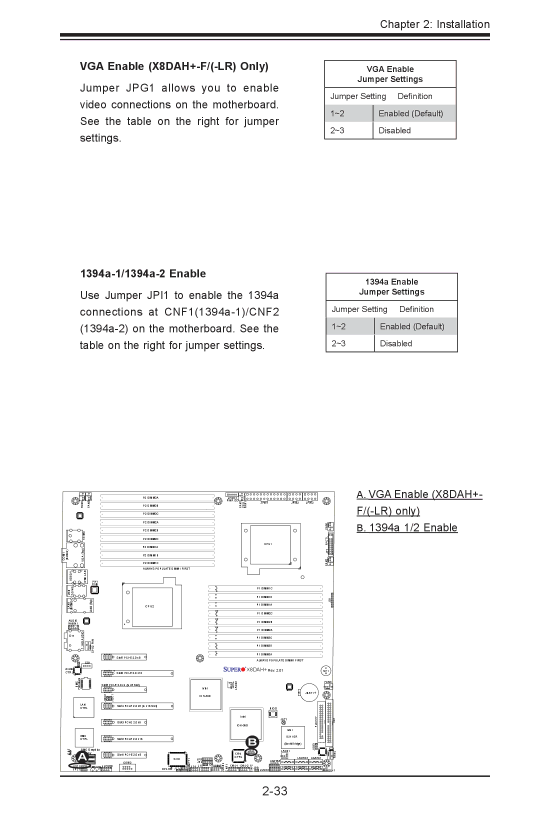
VGA Enable (X8DAH+-F/(-LR) Only)
Jumper JPG1 allows you to enable video connections on the motherboard. See the table on the right for jumper settings.
1394a-1/1394a-2 Enable
Use Jumper JPI1 to enable the 1394a connections at
| VGA Enable | |
| Jumper Settings | |
| ||
Jumper Setting Definition | ||
1~2 |
| Enabled (Default) |
| ||
2~3 |
| Disabled |
| ||
|
|
|
| 1394a Enable | |
| Jumper Settings | |
| ||
Jumper Setting Definition | ||
1~2 |
| Enabled (Default) |
| ||
2~3 |
| Disabled |
| ||
|
|
|
|
| P2 DIMM3A | JPI2C1 |
|
|
|
FAN6 | FAN5 | P2 DIMM3B | PWR I2C |
|
|
|
FAN7 CPU FAN1 | JPW1 | JPW2 | JPW3 |
P2 DIMM3C
A. VGA Enable (X8DAH+- |
|
| KB/MS |
|
COM1 (Bottom) | VGA (Top) |
|
USB0/1 | IPMI LAN | PHY |
USB 2/3/4/5 |
| Chip |
| LAN2(Top) | |
(Bottom) |
| |
LAN1 |
|
|
AUDIO |
|
|
Header |
|
|
| 7.1HD AUDIO | CPU2 FAN |
| CD1 | |
Audio |
|
|
CTRL |
|
|
P2 DIMM2A
P2 DIMM2B
P2 DIMM2C
P2 DIMM1A
P2 DIMM1B
P2 DIMM1C
ALWAYS POPULATE DIMM1 FIRST
CPU2
Slot7
Slot6
CPU1 |
P1 DIMM1C
P1 DIMM1B
P1 DIMM1A
P1 DIMM2C
P1 DIMM2B
P1 DIMM2A
P1 DIMM3C
P1 DIMM3B
P1 DIMM3A
ALWAYS POPULATE DIMM1 FIRST
![]()
![]()
![]()
![]()
![]()
![]() X8DAH+ Rev. 2.01
X8DAH+ Rev. 2.01
JD1
FAN2 JF1 FPCTL FAN1
SP1
B. 1394a 1/2 Enable |
| Firmware |
|
|
| BMC | Slot5 | |
|
| JI2C2 | JI2C1 |
| LAN |
| Slot4 |
| CTRL |
|
|
|
|
| Slot3 |
| BMC |
|
|
| CTRL |
| Slot2 |
DP5 | BMC Graphics |
| |
A | Memory | Slot1 | |
| A | 1 | |
|
| ||
|
| COM2 | |
| JPG1 | SMBUS1 JLPC80 | |
| JPL1 |
|
|
DP4 ![]()
![]()
![]()
|
|
|
|
|
|
|
| FAN3 | |
|
|
| Intel |
|
|
|
|
| |
|
|
|
|
|
|
| JBAT1 |
| |
|
|
|
|
|
|
|
|
| |
|
|
|
|
|
|
| BIOS |
|
|
|
|
|
| Intel |
|
| JBT1 | FLOPPY | IDE |
|
|
|
|
|
| ||||
|
|
|
|
|
|
| Intel |
|
|
|
|
|
| B | ICH 10R |
|
| ||
|
|
|
| (SouthBridge) | JIDE1 |
| |||
|
|
|
|
| |||||
|
|
|
| JPI1 |
| FAN4 | |||
|
|
|
| 1394 |
|
|
|
| |
S I/O | JPT1 | J14 | JP5 | CTRL |
|
| |||
| J15 J139USB6/7 |
|
| JUSB5 |
| ||||
|
|
| JP4 |
|
|
|
|
| |
JL1 JWD1 |
| JUSB4 CNF1 |
| CNF2 | JP9 JUSB2 | JOH1 | |||