Chapter 2: Installation
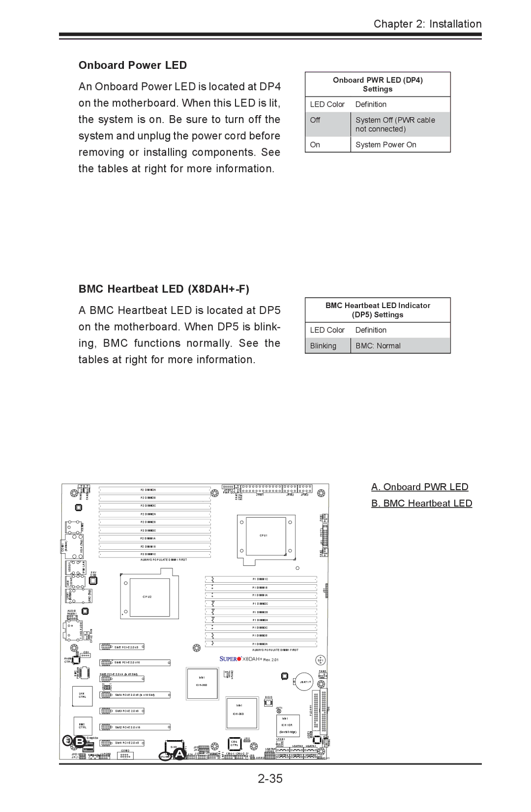
Onboard Power LED
An Onboard Power LED is located at DP4 on the motherboard. When this LED is lit, the system is on. Be sure to turn off the system and unplug the power cord before removing or installing components. See the tables at right for more information.
BMC Heartbeat LED (X8DAH+-F)
A BMC Heartbeat LED is located at DP5 on the motherboard. When DP5 is blink- ing, BMC functions normally. See the tables at right for more information.
Onboard PWR LED (DP4)
Settings
LED Color |
| Definition |
Off |
| System Off (PWR cable |
| ||
|
| not connected) |
On |
| System Power On |
| ||
|
|
|
BMC Heartbeat LED Indicator
(DP5) Settings
LED Color |
| Definition |
Blinking |
| BMC: Normal |
| ||
|
|
|
|
| P2 DIMM3A | JPI2C1 |
|
|
|
FAN6 | FAN5 | P2 DIMM3B | PWR I2C |
|
|
|
FAN7 CPU FAN1 | JPW1 | JPW2 | JPW3 |
A. Onboard PWR LED B. BMC Heartbeat LED
| KB/MS |
|
COM1 (Bottom) | VGA (Top) |
|
USB0/1 | IPMI LAN | PHY |
USB 2/3/4/5 |
| Chip |
| LAN2(Top) | |
(Bottom) |
| |
LAN1 |
|
|
AUDIO |
|
|
Header |
|
|
| 7.1HD AUDIO | CPU2 FAN |
| CD1 | |
Audio |
|
|
CTRL |
|
|
P2 DIMM3C
P2 DIMM2A
P2 DIMM2B
P2 DIMM2C
P2 DIMM1A
P2 DIMM1B
P2 DIMM1C
ALWAYS POPULATE DIMM1 FIRST
CPU2
Slot7
Slot6
CPU1 |
P1 DIMM1C
P1 DIMM1B
P1 DIMM1A
P1 DIMM2C
P1 DIMM2B
P1 DIMM2A
P1 DIMM3C
P1 DIMM3B
P1 DIMM3A
ALWAYS POPULATE DIMM1 FIRST
![]()
![]()
![]()
![]()
![]()
![]() X8DAH+ Rev. 2.01
X8DAH+ Rev. 2.01
JD1
FAN2 JF1 FPCTL FAN1
SP1
| Firmware |
|
|
| BMC | Slot5 | |
|
| JI2C2 | JI2C1 |
| LAN |
| Slot4 |
| CTRL |
|
|
|
|
| Slot3 |
| BMC |
|
|
| CTRL |
| Slot2 |
| B | 1 |
|
DP5 | MC Graphics |
| |
A | Memory | Slot1 | |
|
|
| |
|
|
| COM2 |
| JPG1 | SMBUS1 JLPC80 | |
| JPL1 |
|
|
DP4
|
|
|
|
|
|
|
| FAN3 | |
|
| Intel |
|
|
|
|
|
| |
|
|
|
|
|
| JBAT1 |
| ||
|
|
|
|
|
|
|
|
| |
|
|
|
|
|
| BIOS |
|
|
|
|
|
| Intel |
|
|
| JBT1 | FLOPPY | IDE |
|
|
|
|
|
| ||||
|
|
|
|
|
|
| Intel |
|
|
|
|
|
|
|
|
| ICH 10R |
|
|
|
|
|
|
|
|
| (SouthBridge) | JIDE1 |
|
|
|
| JPI1 |
| FAN4 | ||||
|
|
|
|
| |||||
|
|
| 1394 |
|
|
|
|
| |
S I/O | JPT1 | JP5 | CTRL |
|
| JUSB5 | |||
JL1AJWD1 J14 | JP4 |
| CNF2 | JP9 | JOH1 | ||||
JUSB4 CNF1 | JUSB2 | ||||||||
|
| J15 J139USB6/7 |
|
|
|
|
|
| |