Chapter 2: Installation
2-6 Connecting Cables
Power Connectors
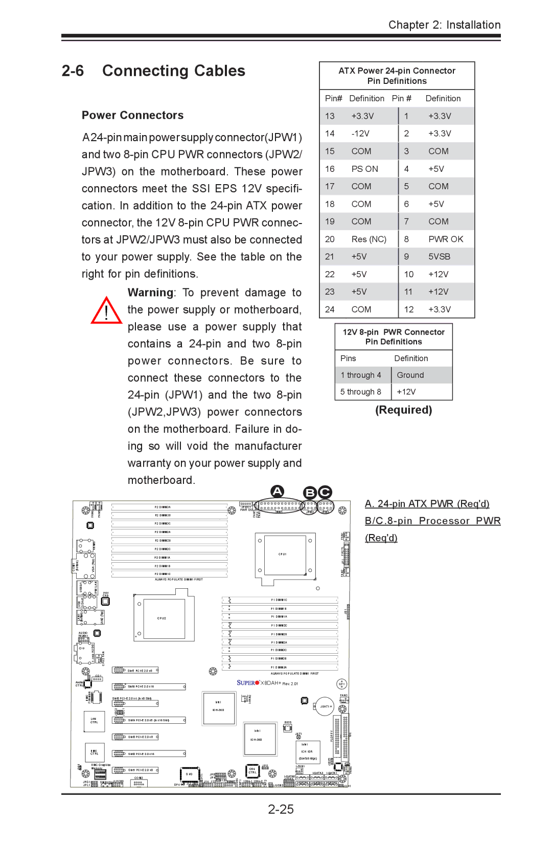
Warning: To prevent damage to the power supply or motherboard, please use a power supply that contains a
A
ATX Power
Pin Definitions
Pin# | Definition |
| Pin # | Definition | |||
13 |
| +3.3V |
|
| +3.3V | ||
|
|
| 1 | ||||
14 |
|
|
|
| +3.3V | ||
|
|
| 2 | ||||
15 |
| COM |
|
|
| COM | |
|
|
| 3 | ||||
16 |
| PS ON |
|
|
| +5V | |
|
|
| 4 | ||||
17 |
| COM |
|
|
| COM | |
|
|
| 5 | ||||
18 |
| COM |
|
|
| +5V | |
|
|
| 6 | ||||
19 |
| COM |
|
|
| COM | |
|
|
| 7 | ||||
20 |
| Res (NC) |
|
|
| PWR OK | |
|
|
| 8 | ||||
21 |
| +5V |
|
|
| 5VSB | |
|
|
| 9 | ||||
22 |
| +5V |
|
|
| +12V | |
|
|
| 10 | ||||
23 |
| +5V |
|
| 11 | +12V | |
24 |
| COM |
|
| 12 | +3.3V | |
|
|
|
|
|
| ||
|
|
|
| ||||
|
| 12V |
| ||||
|
| Pin Definitions |
|
| |||
| Pins |
| Definition |
| |||
| 1 through 4 |
| Ground |
|
| ||
|
|
|
| ||||
| 5 through 8 |
| +12V |
|
| ||
|
|
|
| ||||
|
|
|
|
|
|
|
|
(Required)
BC
| FAN6 | FAN5 |
| KB/MS |
|
COM1 (Bottom) | VGA (Top) |
|
USB0/1 | IPMI LAN | PHY |
USB 2/3/4/5 |
| Chip |
| LAN2(Top) | |
(Bottom) |
| |
LAN1 |
|
|
AUDIO |
|
|
Header |
|
|
| 7.1HD AUDIO | CPU2 FAN |
| CD1 | |
Audio |
|
|
CTRL |
|
|
P2 DIMM3A
P2 DIMM3B
P2 DIMM3C
P2 DIMM2A
P2 DIMM2B
P2 DIMM2C
P2 DIMM1A
P2 DIMM1B
P2 DIMM1C
ALWAYS POPULATE DIMM1 FIRST
CPU2
Slot7
Slot6
JPI2C1 |
|
|
|
PWR I2C |
|
|
|
FAN7 CPU FAN1 | JPW1 | JPW2 | JPW3 |
| FAN1 |
CPU1 | FPCTL |
| JF1 |
| FAN2 |
P1 DIMM1C |
|
P1 DIMM1B | JD1 |
| |
P1 DIMM1A |
|
P1 DIMM2C |
|
P1 DIMM2B |
|
P1 DIMM2A |
|
P1 DIMM3C |
|
P1 DIMM3B |
|
P1 DIMM3A |
|
ALWAYS POPULATE DIMM1 FIRST |
|
X8DAH+ Rev. 2.01 | SP1 |
A.24-pin ATX PWR (Req'd) B/C.8-pin Processor PWR (Req'd)
| Firmware |
|
|
| BMC | Slot5 | |
|
| JI2C2 | JI2C1 |
| LAN |
| Slot4 |
| CTRL |
|
|
|
|
| Slot3 |
| BMC |
|
|
| CTRL |
| Slot2 |
DP5 | BMC Graphics |
| |
A | Memory | Slot1 | |
|
| 1 |
|
|
|
| COM2 |
| JPG1 | SMBUS1 JLPC80 | |
| JPL1 |
|
|
DP4 ![]()
![]()
![]()
|
|
|
|
|
|
|
| FAN3 | |
|
|
| Intel |
|
|
|
|
| |
|
|
|
|
|
|
| JBAT1 |
| |
|
|
|
|
|
|
|
|
| |
|
|
|
|
|
|
| BIOS |
|
|
|
|
|
| Intel |
|
| JBT1 | FLOPPY | IDE |
|
|
|
|
|
| ||||
|
|
|
|
|
|
| Intel |
|
|
|
|
|
|
|
|
| ICH 10R |
|
|
|
|
|
|
|
|
| (SouthBridge) | JIDE1 |
|
|
|
|
| JPI1 | FAN4 | ||||
|
|
|
|
| |||||
|
|
|
| 1394 |
|
|
|
| |
S I/O | JPT1 | J14 | JP5 | CTRL |
|
| |||
| J15 J139USB6/7 |
|
| JUSB5 |
| ||||
|
|
| JP4 |
|
|
|
|
| |
JL1 JWD1 |
| JUSB4 CNF1 |
| CNF2 | JP9 JUSB2 | JOH1 | |||
