A+ SERVER
5-12 IDE and SATA Drive Connections
Use the following information to connect the IDE hard disk drive cables.
•A red mark on a wire typically designates the location of pin 1.
•
IDE Connector
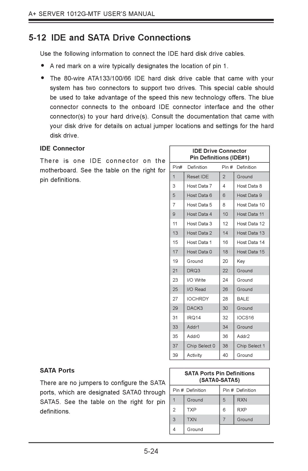
There is one IDE connector on the motherboard. See the table on the right for pin definitions.
IDE Drive Connector
Pin Definitions (IDE#1)
Pin# | Definition | Pin # | Definition |
|
|
|
|
1 | Reset IDE | 2 | Ground |
3 | Host Data 7 | 4 | Host Data 8 |
5 | Host Data 6 | 6 | Host Data 9 |
7 | Host Data 5 | 8 | Host Data 10 |
9 | Host Data 4 | 10 | Host Data 11 |
11 | Host Data 3 | 12 | Host Data 12 |
13 | Host Data 2 | 14 | Host Data 13 |
15 | Host Data 1 | 16 | Host Data 14 |
17 | Host Data 0 | 18 | Host Data 15 |
19 | Ground | 20 | Key |
21 | DRQ3 | 22 | Ground |
23 | I/O Write | 24 | Ground |
25 | I/O Read | 26 | Ground |
27 | IOCHRDY | 28 | BALE |
29 | DACK3 | 30 | Ground |
31 | IRQ14 | 32 | IOCS16 |
33 | Addr1 | 34 | Ground |
35 | Addr0 | 36 | Addr2 |
37 | Chip Select 0 | 38 | Chip Select 1 |
39 | Activity | 40 | Ground |
|
|
|
|
SATA Ports
There are no jumpers to configure the SATA ports, which are designated SATA0 through SATA5. See the table on the right for pin definitions.
SATA Ports Pin Definitions
Pin # | Definition | Pin # | Definition |
|
|
|
|
1 | Ground | 5 | RXN |
2 | TXP | 6 | RXP |
3 | TXN | 7 | Ground |
4 | Ground |
|
|
|
| ||
|
|
|
|
