Chapter 5: Advanced Serverboard Setup
3.Use your thumb and your index fi nger to hold the CPU at opposite sides.
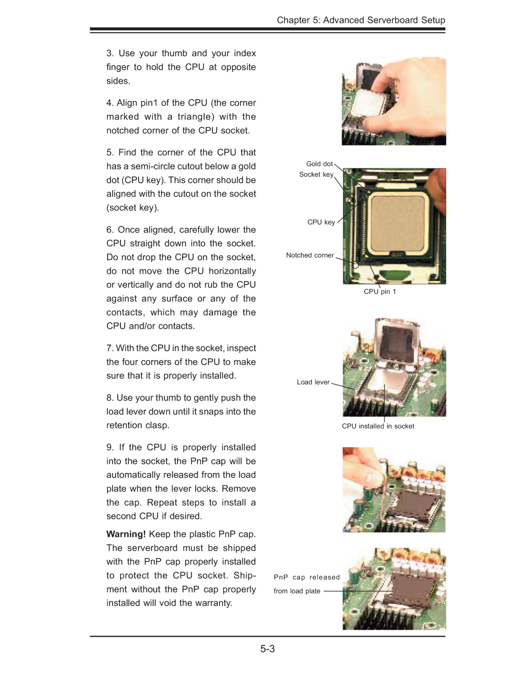
4.Align pin1 of the CPU (the corner marked with a triangle) with the notched corner of the CPU socket.
5.Find the corner of the CPU that has a
6.Once aligned, carefully lower the CPU straight down into the socket. Do not drop the CPU on the socket, do not move the CPU horizontally or vertically and do not rub the CPU against any surface or any of the contacts, which may damage the CPU and/or contacts.
7.With the CPU in the socket, inspect the four corners of the CPU to make sure that it is properly installed.
8.Use your thumb to gently push the load lever down until it snaps into the retention clasp.
9.If the CPU is properly installed into the socket, the PnP cap will be automatically released from the load plate when the lever locks. Remove the cap. Repeat steps to install a second CPU if desired.
Warning! Keep the plastic PnP cap. The serverboard must be shipped with the PnP cap properly installed to protect the CPU socket. Ship- ment without the PnP cap properly installed will void the warranty.
Gold dot
Socket key
CPU key
Notched corner
CPU pin 1
Load lever
CPU installed in socket
PnP cap released
from load plate