![]()
![]()
![]()
![]()
![]()
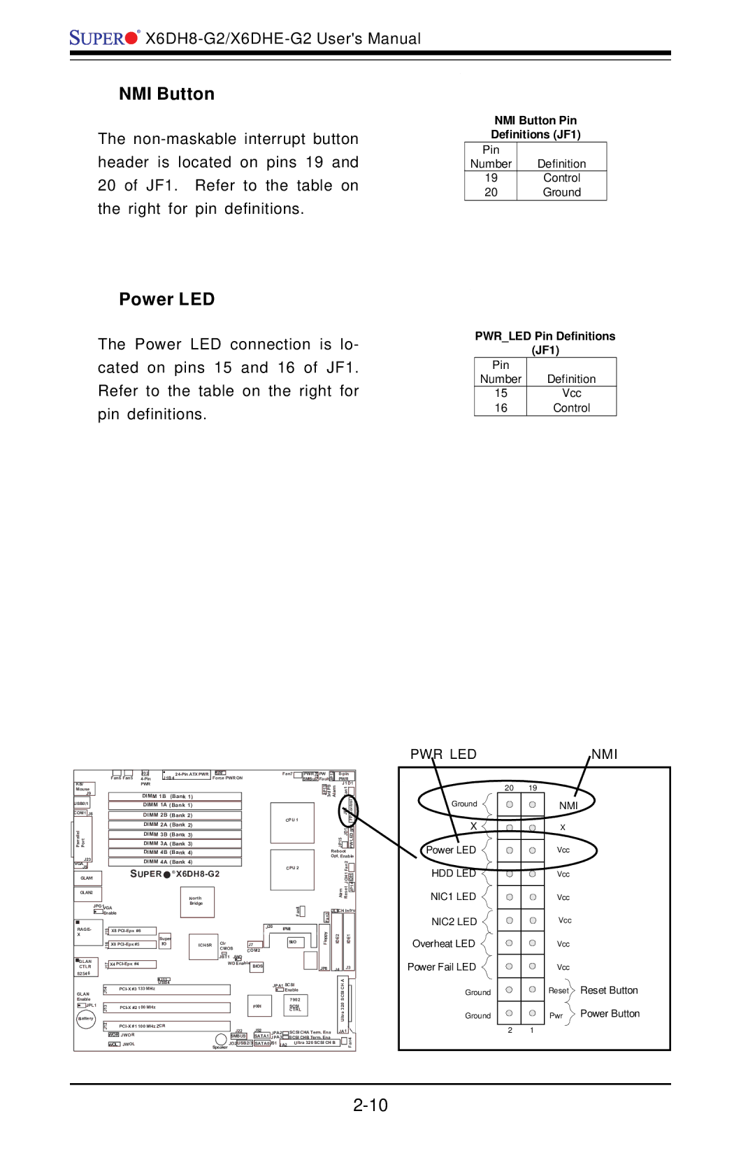
NMI Button
The
NMI Button Pin Definitions (JF1)
Pin
Number Definition
19Control
20Ground
Power LED
The Power LED connection is lo- cated on pins 15 and 16 of JF1. Refer to the table on the right for pin definitions.
PWR_LED Pin Definitions
(JF1)
Pin |
|
Number | Definition |
15 | Vcc |
16 | Control |
PWR LED | NMI |
|
|
|
|
|
|
|
|
|
|
|
|
|
|
|
|
|
|
|
|
|
|
|
|
|
|
|
|
|
|
|
|
|
|
| J32 |
|
|
|
| JPF |
|
|
|
|
|
| |||
|
|
|
|
|
|
|
|
|
|
|
|
| J1B4 |
|
|
| Force PWR ON | |||||||
|
|
|
|
|
|
| Fan6 Fan5 |
|
|
|
|
| ||||||||||||
|
|
|
|
|
|
|
|
|
|
|
|
|
|
|
| |||||||||
KB/ |
|
|
|
|
|
|
| PWR |
|
|
|
|
|
|
|
|
|
|
|
|
| |||
Mouse |
|
|
|
|
|
|
|
|
|
|
|
|
|
|
|
|
|
|
|
|
|
| ||
J9 |
|
|
|
|
|
|
| DIMM 1B | (Bank 1) |
|
|
|
|
|
|
| ||||||||
USB0/1 |
|
|
|
|
|
|
|
| DIMM 1A (Bank 1) |
|
|
|
|
|
|
| ||||||||
|
|
|
|
|
|
|
|
|
|
|
|
|
|
|
|
|
|
|
|
|
|
|
| |
COM1 | J6 |
|
|
|
|
|
|
| DIMM 2B (Bank 2) |
|
|
|
|
|
|
| ||||||||
|
|
|
|
|
|
|
|
|
| DIMM 2A (Bank 2) |
|
|
|
|
|
|
| |||||||
Parrallel Port |
|
|
|
|
|
|
|
|
| DIMM 3A | (Bank 3) |
|
|
|
|
|
|
| ||||||
|
|
|
|
|
|
|
|
|
| DIMM 3B | (Bank 3) |
|
|
|
|
|
|
| ||||||
|
|
|
|
|
|
|
|
|
|
|
|
|
|
|
|
|
|
| ||||||
|
|
|
|
|
|
|
|
|
| DIMM 4B (Bank 4) |
|
|
|
|
|
|
| |||||||
J23 |
|
|
|
|
|
|
| DIMM 4A (Bank 4) |
|
|
|
|
|
|
| |||||||||
VGA |
|
|
|
|
|
|
|
|
|
|
|
|
|
|
|
| ||||||||
J5 |
|
|
|
|
|
|
| SUPER | ® |
|
|
|
|
|
| |||||||||
|
|
|
|
|
|
|
|
|
|
|
|
| ||||||||||||
GLAN1 |
|
|
|
|
|
|
|
|
|
|
| |||||||||||||
|
|
|
|
|
|
|
|
|
|
|
|
|
|
|
|
|
|
|
|
|
|
|
|
|
GLAN2 |
|
|
|
|
|
|
|
|
|
|
|
|
|
| North |
|
|
|
|
|
|
| ||
|
|
|
|
|
|
|
|
|
|
|
|
|
|
|
|
|
|
|
|
|
|
|
| |
|
|
| JPG1 | VGA |
|
|
|
|
|
|
| Bridge |
|
|
|
|
|
|
| |||||
|
|
|
|
|
|
|
|
|
|
|
|
|
|
|
|
|
| |||||||
|
|
|
|
| Enable |
|
|
|
|
|
|
|
|
|
|
|
|
|
| J20 | ||||
|
|
|
|
|
|
|
|
|
|
|
|
|
|
|
|
|
|
|
|
|
|
|
| |
RAGE- |
|
| J15 |
| X8 |
|
|
|
|
|
|
|
|
|
|
|
| |||||||
X |
|
|
|
|
|
|
|
|
|
|
|
|
|
|
|
|
|
|
|
|
| |||
|
|
|
|
|
|
|
| Super |
|
|
|
| Clr |
|
|
|
|
| ||||||
|
|
|
|
| J16 |
| X8 |
|
| I/O |
|
|
| ICH5R |
|
| J7 |
| ||||||
|
|
|
|
|
|
|
|
|
|
|
|
|
|
| CMOS | |||||||||
|
|
|
|
|
|
|
|
|
|
|
|
|
|
|
|
|
| COM2 | ||||||
|
|
|
|
|
|
|
|
|
|
|
|
|
|
|
|
|
| JBT1 | JWD | |||||
GLAN |
|
| J17 |
| X4 |
|
|
|
|
|
|
|
|
| WD Enable | BIOS |
| |||||||
CTLR |
|
|
|
|
|
|
|
|
|
|
|
|
|
|
|
|
|
|
|
| ||||
82546 |
|
|
|
|
|
|
|
|
|
|
|
|
|
|
|
|
|
|
|
|
|
| ||
|
|
|
|
|
|
|
|
|
|
|
|
|
|
|
|
|
|
|
|
|
|
| ||
Fan7 |
|
|
| PWR | ||
|
|
|
|
|
| J24 |
|
|
|
|
| SMBus | |
CPU 1 |
|
|
| |||
|
|
| ||||
CPU 2 |
|
|
| |||
|
|
| ||||
|
|
| ||||
|
| Fan8 |
|
|
|
|
|
|
|
|
|
| |
|
|
|
|
|
| |
IPMI |
|
|
| |||
|
|
| ||||
| SI/O |
|
|
| ||
|
|
|
|
|
|
|
|
|
|
|
|
|
|
|
|
|
|
|
|
|
Fault | JP12 |
| PWR |
|
| ||||||
PW |
|
|
|
| |||||||
|
|
|
|
|
|
| J1D1 |
| |||
|
| JP13 | 3rdPS | Alarm | F |
|
| ||||
|
|
|
|
|
|
| 1 |
|
|
|
|
|
|
|
|
|
|
| n |
|
|
|
|
|
|
|
|
|
|
| a |
|
|
|
|
|
|
|
|
|
|
| JF1 |
| Control |
| |
|
|
|
|
|
|
|
|
|
| FP |
|
|
|
|
|
| JP15 | JD1 |
|
|
|
| |
|
|
|
|
|
|
|
|
|
|
|
|
|
|
|
| Reboot |
|
| |||||
|
|
|
| Opt. Enable | |||||||
|
|
|
|
|
|
| Fan2 |
|
|
|
|
|
|
|
|
|
|
|
|
|
|
| |
|
|
|
|
|
|
| JOH1 |
|
|
|
|
|
|
|
|
|
| Alrm Reset |
| JP14 |
| ||
|
|
|
|
|
|
|
|
| |||
|
|
|
|
|
|
|
|
|
|
|
|
|
| Fan3 | JL1CH Intru | ||||||||
|
|
|
|
|
|
|
|
|
| ||
|
| Floppy |
| IDE2 | IDE1 |
| |||||
| JP8 |
| J4 | J3 |
| ||||||
Ground
X ![]() Power LED
Power LED ![]()
HDD LED
NIC1 LED ![]()
NIC2 LED ![]()
Overheat LED
Power Fail LED
20 | 19 |
| NMI |
| X |
| Vcc |
| Vcc |
| Vcc |
| Vcc |
| Vcc |
| Vcc |
|
|
|
|
|
| J11 |
|
|
|
|
|
|
|
|
|
| A |
| ||
|
|
|
|
|
| USB4 |
|
|
|
|
|
|
|
| ||||||
|
| J14 |
| 133 MHz |
|
|
|
|
| JPA1 SCSI | SCSICH |
| ||||||||
Enable |
|
|
|
|
|
|
| Enable |
| |||||||||||
|
|
|
|
|
|
|
|
|
|
|
| 7902 |
|
| ||||||
GLAN |
|
|
|
|
|
|
|
|
|
|
|
|
|
|
| Ultra320 |
| |||
| JPL1 |
|
|
|
|
|
|
|
|
|
|
|
|
| SCSI |
|
| |||
| J13 |
| 100 MHz |
|
|
| PXH |
|
|
|
|
| ||||||||
|
|
|
|
|
|
|
|
|
| CTRL |
|
| ||||||||
|
|
|
|
|
|
|
|
|
|
|
|
|
|
|
|
| ||||
Battery |
|
|
|
|
|
|
|
|
|
|
|
|
|
|
|
| ||||
|
| J12 |
| 100 MHz ZCR |
| J22 |
| JS2 |
|
|
|
|
|
|
|
|
| |||
|
|
|
|
|
|
|
|
|
| JPA2 | SCSI CHA Term. Ena | JA1 |
|
| ||||||
|
|
|
|
|
|
|
|
|
|
|
|
|
| |||||||
|
|
| WOR JWOR |
|
|
|
| SMBUS |
| SATA1 | JPA3 | SCSI CHB Term. Ena |
|
|
|
| ||||
|
|
|
|
|
|
| Speaker JD2 | USB2/3 | SATA0 | JS1 |
| Ultra 320 SCSI CH B |
|
|
| Fan4 | ||||
|
|
| WOL JWOL |
|
| JA2 |
|
|
| |||||||||||
|
|
|
|
|
|
|
|
|
|
|
|
|
|
|
|
| ||||
Ground
Ground
| Reset | Reset Button |
| Pwr | Power Button |
2 | 1 |
|