Chapter 2: Installation
Top View of DDRII Slot |
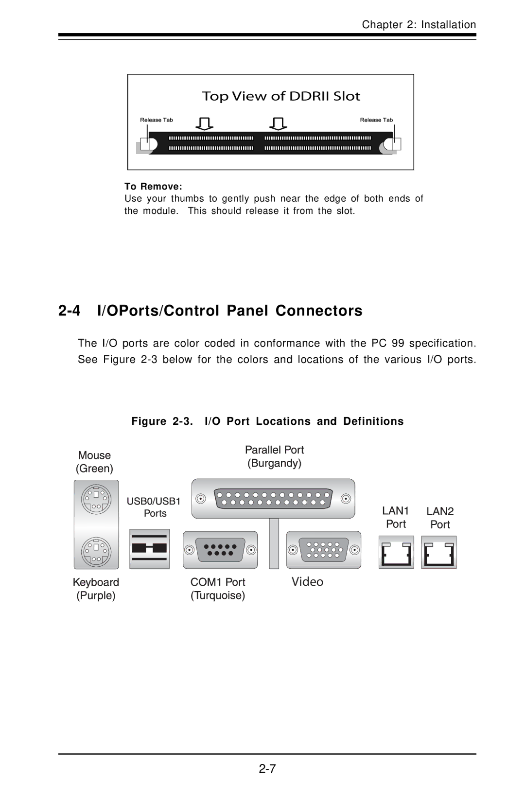
To Remove:
Use your thumbs to gently push near the edge of both ends of the module. This should release it from the slot.
2-4 I/OPorts/Control Panel Connectors
The I/O ports are color coded in conformance with the PC 99 specification. See Figure
