Chapter 2: Installation
Reset Button
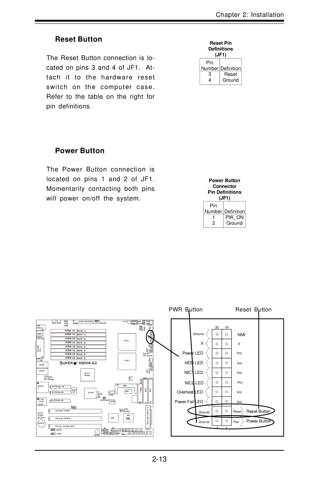
The Reset Button connection is lo- cated on pins 3 and 4 of JF1. At- tach it to the hardware reset switch on the computer case. Refer to the table on the right for pin definitions.
Power Button
The Power Button connection is located on pins 1 and 2 of JF1. Momentarily contacting both pins will power on/off the system.
Reset Pin
Definitions
(JF1)
Pin
Number Definition
3Reset
4Ground
Power Button
Connector
Pin Definitions
(JF1)
Pin
Number Definition
1PW_ON
2Ground
PWR Button | Reset Button |
|
|
|
|
|
|
|
|
|
|
|
|
|
|
|
|
|
|
|
|
|
|
|
|
|
|
|
|
|
|
|
|
|
|
| J32 |
|
|
|
| JPF |
|
|
|
|
|
| |||
|
|
|
|
|
|
|
|
|
|
|
|
| J1B4 |
|
|
| Force PWR ON | |||||||
|
|
|
|
|
|
| Fan6 Fan5 |
|
|
|
|
| ||||||||||||
|
|
|
|
|
|
|
|
|
|
|
|
|
|
|
| |||||||||
KB/ |
|
|
|
|
|
|
| PWR |
|
|
|
|
|
|
|
|
|
|
|
|
| |||
Mouse |
|
|
|
|
|
|
|
|
|
|
|
|
|
|
|
|
|
|
|
|
|
| ||
J9 |
|
|
|
|
|
|
| DIMM 1B | (Bank 1) |
|
|
|
|
|
|
| ||||||||
USB0/1 |
|
|
|
|
|
|
|
| DIMM 1A (Bank 1) |
|
|
|
|
|
|
| ||||||||
|
|
|
|
|
|
|
|
|
|
|
|
|
|
|
|
|
|
|
|
|
|
|
| |
COM1 | J6 |
|
|
|
|
|
|
| DIMM 2B (Bank 2) |
|
|
|
|
|
|
| ||||||||
|
|
|
|
|
|
|
|
|
| DIMM 2A (Bank 2) |
|
|
|
|
|
|
| |||||||
Parrallel Port |
|
|
|
|
|
|
|
|
| DIMM 3A | (Bank 3) |
|
|
|
|
|
|
| ||||||
|
|
|
|
|
|
|
|
|
| DIMM 3B | (Bank 3) |
|
|
|
|
|
|
| ||||||
|
|
|
|
|
|
|
|
|
|
|
|
|
|
|
|
|
|
| ||||||
|
|
|
|
|
|
|
|
|
| DIMM 4B (Bank 4) |
|
|
|
|
|
|
| |||||||
J23 |
|
|
|
|
|
|
| DIMM 4A (Bank 4) |
|
|
|
|
|
|
| |||||||||
VGA |
|
|
|
|
|
|
|
|
|
|
|
|
|
|
|
| ||||||||
J5 |
|
|
|
|
|
|
| SUPER | ® |
|
|
|
|
|
| |||||||||
|
|
|
|
|
|
|
|
|
|
|
|
| ||||||||||||
GLAN1 |
|
|
|
|
|
|
|
|
|
|
| |||||||||||||
|
|
|
|
|
|
|
|
|
|
|
|
|
|
|
|
|
|
|
|
|
|
|
|
|
GLAN2 |
|
|
|
|
|
|
|
|
|
|
|
|
|
| North |
|
|
|
|
|
|
| ||
|
|
|
|
|
|
|
|
|
|
|
|
|
|
|
|
|
|
|
|
|
|
|
| |
|
|
| JPG1 | VGA |
|
|
|
|
|
|
| Bridge |
|
|
|
|
|
|
| |||||
|
|
|
|
|
|
|
|
|
|
|
|
|
|
|
|
|
| |||||||
|
|
|
|
| Enable |
|
|
|
|
|
|
|
|
|
|
|
|
|
| J20 | ||||
|
|
|
|
|
|
|
|
|
|
|
|
|
|
|
|
|
|
|
|
|
|
|
| |
RAGE- |
|
| J15 |
| X8 |
|
|
|
|
|
|
|
|
|
|
|
| |||||||
X |
|
|
|
|
|
|
|
|
|
|
|
|
|
|
|
|
|
|
|
|
| |||
|
|
|
|
|
|
|
| Super |
|
|
|
| Clr |
|
|
|
|
| ||||||
|
|
|
|
| J16 |
| X8 |
|
| I/O |
|
|
| ICH5R |
|
| J7 |
| ||||||
|
|
|
|
|
|
|
|
|
|
|
|
|
|
| CMOS | |||||||||
|
|
|
|
|
|
|
|
|
|
|
|
|
|
|
|
|
| COM2 | ||||||
|
|
|
|
|
|
|
|
|
|
|
|
|
|
|
|
|
| JBT1 | JWD | |||||
GLAN |
|
| J17 |
| X4 |
|
|
|
|
|
|
|
|
| WD Enable | BIOS |
| |||||||
CTLR |
|
|
|
|
|
|
|
|
|
|
|
|
|
|
|
|
|
|
|
| ||||
82546 |
|
|
|
|
|
|
|
|
|
|
|
|
|
|
|
|
|
|
|
|
|
| ||
|
|
|
|
|
|
|
|
|
|
|
|
|
|
|
|
|
|
|
|
|
|
| ||
Fan7 |
|
|
| PWR | ||
|
|
|
|
|
| J24 |
|
|
|
|
| SMBus | |
CPU 1 |
|
|
| |||
|
|
| ||||
CPU 2 |
|
|
| |||
|
|
| ||||
|
|
| ||||
|
| Fan8 |
|
|
|
|
|
|
|
|
|
| |
|
|
|
|
|
| |
IPMI |
|
|
| |||
|
|
| ||||
| SI/O |
|
|
| ||
|
|
|
|
|
|
|
|
|
|
|
|
|
|
|
|
|
|
|
|
|
Fault | JP12 |
| PWR |
|
| ||||||
PW |
|
|
|
| |||||||
|
|
|
|
|
|
| J1D1 |
| |||
|
| JP13 | 3rdPS | Alarm | F |
|
| ||||
|
|
|
|
|
|
| 1 |
|
|
|
|
|
|
|
|
|
|
| n |
|
|
|
|
|
|
|
|
|
|
| a |
|
|
|
|
|
|
|
|
|
|
| JF1 |
| Control |
| |
|
|
|
|
|
|
|
|
|
| FP |
|
|
|
|
|
| JP15 | JD1 |
|
|
|
| |
|
|
|
|
|
|
|
|
|
|
|
|
|
|
|
| Reboot |
|
| |||||
|
|
|
| Opt. Enable | |||||||
|
|
|
|
|
|
| Fan2 |
|
|
|
|
|
|
|
|
|
|
|
|
|
|
| |
|
|
|
|
|
|
| JOH1 |
|
|
|
|
|
|
|
|
|
| Alrm Reset |
| JP14 |
| ||
|
|
|
|
|
|
|
|
| |||
|
|
|
|
|
|
|
|
|
|
|
|
|
| Fan3 | JL1CH Intru | ||||||||
|
|
|
|
|
|
|
|
|
| ||
|
| Floppy |
| IDE2 | IDE1 |
| |||||
| JP8 |
| J4 | J3 |
| ||||||
Ground
X ![]() Power LED
Power LED ![]()
HDD LED
NIC1 LED ![]()
NIC2 LED ![]()
Overheat LED
Power Fail LED
20 | 19 |
| NMI |
| X |
| Vcc |
| Vcc |
| Vcc |
| Vcc |
| Vcc |
| Vcc |
|
|
|
|
|
| J11 |
|
|
|
|
|
|
|
|
|
| A |
| ||
|
|
|
|
|
| USB4 |
|
|
|
|
|
|
|
| ||||||
|
| J14 |
| 133 MHz |
|
|
|
|
| JPA1 SCSI | SCSICH |
| ||||||||
Enable |
|
|
|
|
|
|
| Enable |
| |||||||||||
|
|
|
|
|
|
|
|
|
|
|
| 7902 |
|
| ||||||
GLAN |
|
|
|
|
|
|
|
|
|
|
|
|
|
|
| Ultra320 |
| |||
| JPL1 |
|
|
|
|
|
|
|
|
|
|
|
|
| SCSI |
|
| |||
| J13 |
| 100 MHz |
|
|
| PXH |
|
|
|
|
| ||||||||
|
|
|
|
|
|
|
|
|
| CTRL |
|
| ||||||||
|
|
|
|
|
|
|
|
|
|
|
|
|
|
|
|
| ||||
Battery |
|
|
|
|
|
|
|
|
|
|
|
|
|
|
|
| ||||
|
| J12 |
| 100 MHz ZCR | J22 |
| JS2 |
|
|
|
|
|
|
|
|
| ||||
|
|
|
|
|
|
|
|
| JPA2 | SCSI CHA Term. Ena | JA1 |
|
| |||||||
|
|
|
|
|
|
|
|
|
|
|
|
| ||||||||
|
|
| WOR JWOR |
|
|
| SMBUS |
| SATA1 | JPA3 | SCSI CHB Term. Ena |
|
|
|
| |||||
|
|
|
|
|
|
| Speaker JD2 | USB2/3 | SATA0 | JS1 |
| Ultra 320 SCSI CH B |
|
|
| Fan4 | ||||
|
|
| WOL JWOL |
|
| JA2 |
|
|
| |||||||||||
|
|
|
|
|
|
|
|
|
|
|
|
|
|
|
|
| ||||
Ground
Ground
| Reset | Reset Button |
| Pwr | Power Button |
2 | 1 |
|