Quick Start — MVX VGA A Matrix Switchers
Installation
Step 1
Turn off power to the input and output devices, and disconnect their power cords.
Step 2 — Inputs
a. Connect up to 16 high resolution
video inputs to the
b. Connect up to 16 stereo or mono audio inputs to the
Tip | Tip | L | |
Sleeve | Ring | ||
| |||
| Sleeve (s) |
| |
Tip | Tip | R | |
Sleeve | Ring | ||
|
Unbalanced Input | Balanced Input |
(high impedance) | (high impedance) |
Step 3 — Outputs
a. Connect up to 16 high resolution video devices to the
b. Connect up to 16 balanced or unbalanced stereo audio or mono audio devices to the
Tip | Tip | L | |
NO GROUND HERE. | Ring | ||
| |||
Sleeve(s) | Sleeve(s) |
| |
Tip | Tip | R | |
NO GROUND HERE. | Ring | ||
|
Unbalanced Output | Balanced Output |
CAUTION Connect the sleeve to ground. Connecting the sleeve to a negative
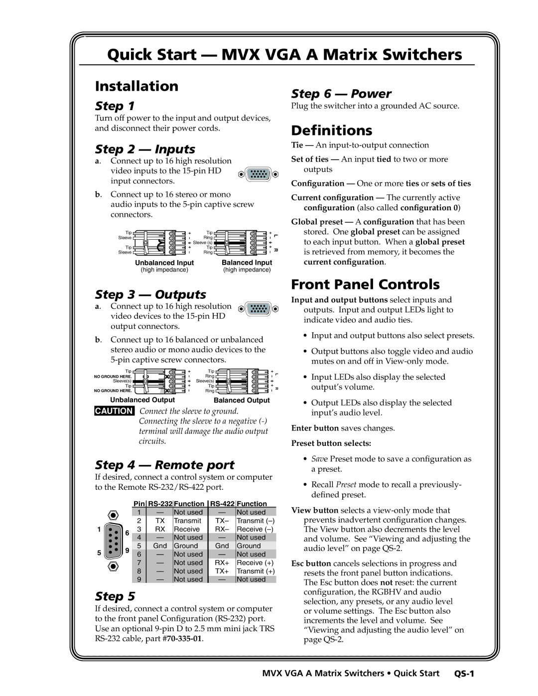
Step 4 — Remote port
If desired, connect a control system or computer to the Remote
|
| Pin | ||||
|
| 1 | — | Not used | — | Not used |
|
| 2 | TX | Transmit | TX– | Transmit |
1 | 6 | 3 | RX | Receive | RX– | Receive |
|
| 4 | — | Not used | — | Not used |
5 | 9 | 5 | Gnd | Ground | Gnd | Ground |
6 | — | Not used | — | Not used | ||
|
| 7 | — | Not used | RX+ | Receive (+) |
|
| 8 | — | Not used | TX+ | Transmit (+) |
|
| 9 | — | Not used | — | Not used |
Step 5
If desired, connect a control system or computer to the front panel Configuration
Step 6 — Power
Plug the switcher into a grounded AC source.
Definitions
Tie — An
Set of ties — An input tied to two or more outputs
Configuration — One or more ties or sets of ties
Current configuration — The currently active configuration (also called configuration 0)
Global preset — A configuration that has been stored. One global preset can be assigned to each input button. When a global preset is retrieved from memory, it becomes the current configuration.
Front Panel Controls
Input and output buttons select inputs and
outputs. Input and output LEDs light to indicate video and audio ties.
•Input and output buttons also select presets.
•Output buttons also toggle video and audio mutes on and off in
•Input LEDs also display the selected output’s volume.
•Output LEDs also display the selected input’s audio level.
Enter button saves changes.
Preset button selects:
•Save Preset mode to save a configuration as a preset.
•Recall Preset mode to recall a previously- defined preset.
View button selects a
Esc button cancels selections in progress and resets the front panel button indications. The Esc button does not reset: the current configuration, the RGBHV and audio selection, any presets, or any audio level or volume settings. The Esc button also increments the level and volume. See “Viewing and adjusting the audio level” on page