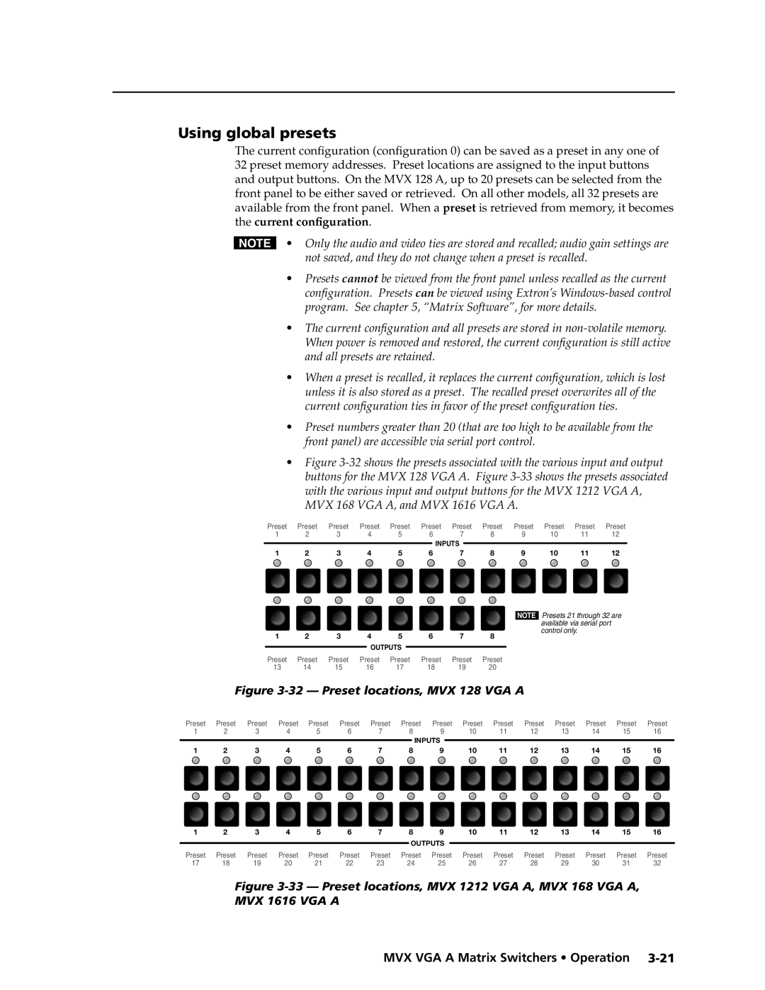
Using global presets
The current configuration (configuration 0) can be saved as a preset in any one of 32 preset memory addresses. Preset locations are assigned to the input buttons and output buttons. On the MVX 128 A, up to 20 presets can be selected from the front panel to be either saved or retrieved. On all other models, all 32 presets are available from the front panel. When a preset is retrieved from memory, it becomes the current configuration.
N• Only the audio and video ties are stored and recalled; audio gain settings are not saved, and they do not change when a preset is recalled.
•Presets cannot be viewed from the front panel unless recalled as the current configuration. Presets can be viewed using Extron’s
•The current configuration and all presets are stored in
•When a preset is recalled, it replaces the current configuration, which is lost unless it is also stored as a preset. The recalled preset overwrites all of the current configuration ties in favor of the preset configuration ties.
•Preset numbers greater than 20 (that are too high to be available from the front panel) are accessible via serial port control.
•Figure 3-32 shows the presets associated with the various input and output buttons for the MVX 128 VGA A. Figure 3-33 shows the presets associated with the various input and output buttons for the MVX 1212 VGA A, MVX 168 VGA A, and MVX 1616 VGA A.
Preset | Preset | Preset |
| Preset | Preset | Preset |
| Preset | Preset |
| Preset | Preset | Preset | Preset | ||||||||||||||
1 | 2 | 3 | 4 |
| 5 | 6 | 7 |
|
| 8 | 9 |
| 10 | 11 | 12 | |||||||||||||
|
|
|
|
|
|
|
|
|
|
|
|
| INPUTS |
|
|
|
|
|
|
|
|
|
|
|
|
| ||
|
|
|
|
|
|
|
|
|
|
|
|
|
|
|
|
|
|
|
|
|
|
|
|
|
| |||
1 | 2 | 3 | 4 |
| 5 | 6 | 7 |
|
| 8 | 9 |
| 10 | 11 | 12 | |||||||||||||
|
|
|
|
|
|
|
|
|
|
|
|
|
|
|
|
|
|
|
|
|
|
|
|
|
|
|
|
|
|
|
|
|
|
|
|
|
|
|
|
|
|
|
|
|
|
|
|
|
|
|
|
|
|
|
|
|
|
|
|
|
|
|
|
|
|
|
|
|
|
|
|
|
|
|
|
|
|
|
|
|
|
|
|
|
|
|
|
|
|
|
|
|
|
| Presets 21 through 32 are |
|
|
| |||||||
|
|
|
|
|
|
|
|
|
|
|
|
|
|
|
|
|
|
|
|
|
|
|
|
|
|
|
|
|
|
|
|
|
|
| NOTE |
|
|
| |||||||||
|
|
|
|
|
|
|
|
|
|
|
|
|
|
|
|
|
|
|
|
|
|
|
|
|
|
|
|
|
|
|
|
|
|
|
|
| available via serial port |
|
|
|
| ||||||
|
|
|
|
|
| 1 |
| 2 |
|
| 3 |
| 4 |
| 5 |
|
| 6 |
|
| 7 |
| 8 |
|
|
|
|
| control only. |
|
|
|
|
|
|
| |||||||||||
|
|
|
|
|
|
|
|
|
|
|
|
|
|
|
|
|
|
|
|
|
|
|
|
|
|
|
|
|
|
|
| ||||||||||||||||
|
|
|
|
|
|
|
|
|
|
|
|
|
|
|
| OUTPUTS |
|
|
|
|
|
|
|
|
|
|
|
|
|
|
|
|
|
|
|
|
|
|
|
|
|
|
| ||||
|
|
|
|
|
|
|
|
|
|
|
|
|
|
|
|
|
|
|
|
|
|
|
|
|
|
|
|
|
|
|
|
|
|
|
|
|
|
|
|
|
|
| |||||
|
|
|
|
|
| Preset Preset | Preset | Preset Preset | Preset Preset | Preset |
|
|
|
|
|
|
|
|
|
|
|
|
| ||||||||||||||||||||||||
|
|
|
|
|
| 13 |
| 14 |
| 15 |
| 16 |
| 17 |
|
| 18 |
|
| 19 |
| 20 |
|
|
|
|
|
|
|
|
|
|
|
|
|
|
|
| |||||||||
|
|
| Figure |
|
|
|
|
|
|
|
|
|
| ||||||||||||||||||||||||||||||||||
Preset | Preset | Preset |
| Preset | Preset | Preset |
|
| Preset | Preset |
| Preset | Preset | Preset | Preset | Preset | Preset | Preset | Preset |
| |||||||||||||||||||||||||||
1 | 2 | 3 | 4 | 5 | 6 | 7 | 8 | 9 |
| 10 | 11 |
| 12 |
| 13 |
| 14 |
| 15 | 16 |
| ||||||||||||||||||||||||||
|
|
|
|
|
|
|
|
|
|
|
|
|
|
|
|
|
|
|
|
|
| INPUTS |
|
|
|
|
|
|
|
|
|
|
|
|
|
|
|
|
|
|
|
|
|
| |||
|
|
|
|
|
|
|
|
|
|
|
|
|
|
|
|
|
|
|
|
|
|
|
|
|
|
|
|
|
|
|
|
|
|
|
|
|
|
|
|
|
|
|
| ||||
1 | 2 | 3 | 4 | 5 | 6 | 7 | 8 | 9 |
| 10 | 11 |
| 12 |
| 13 |
| 14 |
| 15 | 16 |
| ||||||||||||||||||||||||||
|
|
|
|
|
|
|
|
|
|
|
|
|
|
|
|
|
|
|
|
|
|
|
|
|
|
|
|
|
|
|
|
|
|
|
|
|
|
|
|
|
|
|
|
|
|
|
|
|
|
|
|
|
|
|
|
|
|
|
|
|
|
|
|
|
|
|
|
|
|
|
|
|
|
|
|
|
|
|
|
|
|
|
|
|
|
|
|
|
|
|
|
|
|
|
|
|
|
|
|
|
|
|
|
|
|
|
|
|
|
|
|
|
|
|
|
|
|
|
|
|
|
|
|
|
|
|
|
|
|
|
|
|
|
|
|
|
|
|
|
|
|
|
|
|
|
|
|
|
|
|
|
|
|
|
|
|
|
|
|
|
|
|
|
|
|
|
|
|
|
|
|
|
|
|
|
|
|
|
|
|
|
|
|
|
|
|
|
|
|
|
|
PRELIMINARY
1 | 2 | 3 | 4 | 5 | 6 | 7 | 8 | 9 |
| 10 | 11 | 12 | 13 | 14 | 15 | 16 | |
|
|
|
|
|
|
|
| OUTPUTS |
|
|
|
|
|
|
|
| |
|
|
|
|
|
|
|
|
|
|
|
| Preset | Preset | Preset | Preset | ||
Preset | Preset | Preset | Preset | Preset | Preset | Preset | Preset | Preset | Preset | Preset | Preset | ||||||
17 | 18 | 19 | 20 | 21 | 22 | 23 | 24 | 25 |
| 26 | 27 | 28 | 29 | 30 | 31 | 32 | |