Computer Video VGA and Audio Matrix Switchers
MVX VGA a
Sicherheitsanleitungen Deutsch
Safety Instructions English
Consignes de Sécurité Français
Instrucciones de seguridad Español
FCC Class a Notice
Preset button selects
MVX VGA a Matrix Switchers Quick Start QS-1
Input and output buttons select inputs
QS-2 MVX VGA a Matrix Switchers Quick Start
Saving or recalling a preset
Viewing and adjusting the audio level
Creating a tie
Table of Contents
Table of Contents, cont’d
Appendix a Specifications, Part Numbers, Accessories
MVX VGA a Matrix Switchers Table of Contents Iii
Iv MVX VGA a Matrix Switchers Table of Contents
One
About the MVX VGA a Matrix Switchers
MVX VGA a Matrix Switchers Introduction
About this Manual
Definitions
Features
Tie any input to any or all outputs
Preliminary
Preliminary
Two
UL requirements
Mounting the Switcher
MVX VGA a Matrix Switchers Installation
Mounting instructions
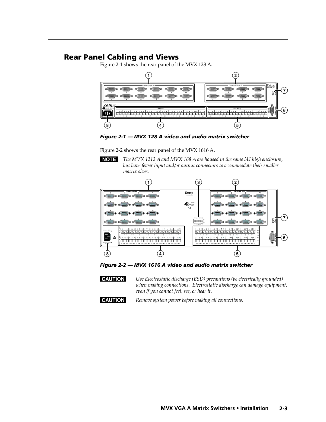
Rear Panel Cabling and Views
Computer OUT
Sync Impedance switches
Video connections
Audio connections
Ohms
RS-232/RS-422 connection
Connections for balanced and unbalanced audio outputs These
Reset button
Power connection
Front Panel Configuration Port
Be used for this connection
Three
Front Panel Controls and Indicators
MVX VGA a Matrix Switchers Operation
Definitions
Input and output buttons
Sample label
Operation, cont’d
Control buttons
Preliminary
Controls
Power
Front Panel Operations
Front panel security lockouts
Creating a configuration
Example 1 Creating a set of video and audio ties
Press and release the Esc button figure
Select the outputs
Example 2 Adding a tie to a set of video and audio ties
Press and release the Input 5 button figure
Press and release the Output 1 button figure
13 Press the Enter button
Example 3 Removing a tie from a set of video and audio ties
15 Clear all selections
Press and release the Output 4 button figure
Press and release the Enter button figure
Viewing a configuration
21 Clear all selections
Preliminary
Rgbhv button and the Audio button figure
24 Deselect Rgbhv to view audio ties only
Muting and unmuting video and/or audio
Example 5 Muting and unmuting an output
28 Select Rgbhv and audio
30 Unmute the outputs
Using global presets
32 Preset locations, MVX 128 VGA a
Example 6 Saving a preset
LED blinks figure
Example 7 Recalling a preset
Press and release the Preset button figure
40 Select the preset
Viewing and adjusting the input audio level
42 Audio gain and attenuation
Example 8 Viewing and adjusting an input audio level
43 Clear all selections
Preliminary
45 Select an input and read the audio level
47 Adjust the input audio level
Viewing and adjusting the output volume
Reading the displayed volume
Audio output volume settings
Example 9 Viewing and adjusting an output volume level
50 Clear all selections
52 Select output
54 Adjust the output audio volume
Setting the front panel locks Executive modes
Selecting Lock mode 2 or toggling between mode 2 and mode
Performing a system reset from the front panel
System reset does not replace user-installed firmware
Selecting the rear panel Remote port protocol and baud rate
Release the Control buttons
61 RS-232/RS-422 and baud rate selection
Performing an absolute system reset from the rear panel
Rear Panel Operations
Performing a hard reset from the rear panel
Optimizing the Audio
Troubleshooting
Configuration Worksheets
Worksheet example 1 System equipment
Worksheet example 2 Daily configuration
66 Worksheet example 2 Daily configuration
Worksheet example 3 Test configuration
Preliminary
Configuration worksheet
Preset #
Preliminary
Four
MVX VGA a Matrix Switchers Programmer’s Guide
Serial Ports
Rear panel Remote port
Host-to-Switcher Instructions
Switcher-Initiated Messages
Front panel Configuration port
Switcher Error Responses
Using the Command/Response Table
Command/Response Table for SIS Commands
Symbol definitions
Command Ascii command Response Additional
Description
% G InX! AudX$
Preliminary
Exng
EZG
EX1$ *X1% ,X1 ,X1& ,X1* CP CpnX1$ CcpX1% ,X1 ,X1& ,X1
VX2XX2!AX2XX2
Five
Matrix Switchers Control Program
Installing the software
MVX VGA a Matrix Switchers Matrix Software
Using the Matrix Switcher Control software
Comm port selection window
Matrix Software, cont’d
Sample program window complete
Location of firmware upgrade files
Updating firmware
Downloading firmware upgrade files
Open window
Firmware Loader status indicator bar
Windows buttons, drop boxes, and trash can
Windows menus
File menu
Tools menu
10 Status window
Master-Reset selection
Preferences menu
Using Emulation mode
Using the help system
Button-Label Generator Program
Using the Button-Label Generator software
14 Extron’s Button-Label Generator window
AppendixAA
Specifications, Part Numbers, Accessories
Specifications
Sync
Specifications, Part Numbers, Accessories, cont’d
Accessories
Part Numbers and Accessories
MVX matrix switcher part numbers
Included parts
Male-to-male VGA molded connector cables Part number
Male-to-female VGA molded connector cables Part number
Male-to-female VGA backshell connector cables Part number
Cables
Preliminary
Button Labels
Preliminary
Preliminary
Extron’s Warranty
Asia Japan
Extron Electronics, Europe Beeldschermweg 6C