![]()
![]()
![]()
![]()
![]()
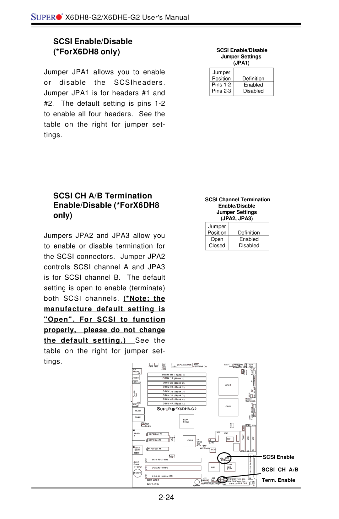
SCSI Enable/Disable (*ForX6DH8 only)
Jumper JPA1 allows you to enable or disable the SCSIheaders. Jumper JPA1 is for headers #1 and #2. The default setting is pins
SCSI CH A/B Termination Enable/Disable (*ForX6DH8 only)
Jumpers JPA2 and JPA3 allow you to enable or disable termination for the SCSI connectors. Jumper JPA2 controls SCSI channel A and JPA3 is for SCSI channel B. The default setting is open to enable (terminate) both SCSI channels. (*Note: the manufacture default setting is "Open". For SCSI to function properly, please do not change the default setting.) See the
SCSI Enable/Disable
Jumper Settings
(JPA1)
Jumper |
|
Position | Definition |
Pins | Enabled |
Pins | Disabled |
|
|
SCSI Channel Termination
Enable/Disable
Jumper Settings
(JPA2, JPA3)
Jumper |
|
Position | Definition |
Open | Enabled |
Closed | Disabled |
|
|
table on the right for jumper set-
tings.
|
|
|
|
|
|
|
|
| J32 |
|
|
|
| JPF |
|
|
|
|
|
| ||||
|
|
|
|
|
|
|
|
|
| J1B4 |
|
|
|
|
|
| ||||||||
|
|
|
|
| Fan6 Fan5 |
|
|
|
|
| Force PWR ON | |||||||||||||
|
|
|
|
|
|
|
|
|
|
|
|
|
|
|
| |||||||||
KB/ |
|
|
|
|
|
|
|
| PWR |
|
|
|
|
|
|
|
|
|
|
|
|
|
| |
Mouse |
|
|
|
|
|
|
|
|
|
|
|
|
|
|
|
|
|
|
|
|
|
| ||
| J9 |
|
|
|
|
|
| DIMM 1B | (Bank 1) |
|
|
|
|
|
|
| ||||||||
USB0/1 |
|
|
|
|
|
| DIMM 1A (Bank 1) |
|
|
|
|
|
|
| ||||||||||
|
|
|
|
|
|
|
|
|
|
|
|
|
|
|
|
|
|
|
|
|
|
|
|
|
COM1 |
| J6 |
|
|
|
|
|
| DIMM 2B (Bank 2) |
|
|
|
|
|
|
| ||||||||
|
|
|
|
|
|
|
|
|
|
|
|
|
|
| ||||||||||
|
|
|
|
|
|
|
|
| DIMM 2A (Bank 2) |
|
|
|
|
|
|
| ||||||||
Parrallel Port |
|
|
|
|
|
|
|
| DIMM 3A | (Bank 3) |
|
|
|
|
|
|
| |||||||
|
|
|
|
|
|
|
|
| DIMM 3B | (Bank 3) |
|
|
|
|
|
|
| |||||||
|
|
|
|
|
|
|
|
|
|
|
|
|
|
|
|
|
| |||||||
|
|
|
|
|
|
|
|
| DIMM 4B (Bank 4) |
|
|
|
|
|
|
| ||||||||
J23 |
|
|
|
|
|
| DIMM 4A (Bank 4) |
|
|
|
|
|
|
| ||||||||||
VGA |
|
|
|
|
|
|
|
|
|
|
|
|
|
|
| |||||||||
J5 |
|
|
|
|
| SUPER | ® |
|
|
|
|
|
| |||||||||||
|
|
|
|
|
|
|
|
|
|
|
| |||||||||||||
GLAN1 |
|
|
|
|
|
|
|
|
|
| ||||||||||||||
|
|
|
|
|
|
|
|
|
|
|
|
|
|
|
|
|
|
|
|
|
|
|
|
|
GLAN2 |
|
|
|
|
|
|
|
|
|
|
|
|
| North |
|
|
|
|
|
|
| |||
|
|
|
|
|
|
|
|
|
|
|
|
|
|
|
|
|
|
|
|
|
|
| ||
|
|
| JPG1 | VGA |
|
|
|
|
|
|
| Bridge |
|
|
|
|
|
|
| |||||
|
|
|
|
|
|
|
|
|
|
|
|
|
|
|
|
|
|
| ||||||
|
|
|
| Enable |
|
|
|
|
|
|
|
|
|
|
|
|
|
|
| J20 | ||||
|
|
|
|
|
|
|
|
|
|
|
|
|
|
|
|
|
|
|
|
|
|
|
| |
RAGE- |
| J15 | X8 |
|
|
|
|
|
|
|
|
|
|
|
|
|
| |||||||
X |
|
|
|
|
|
|
|
|
| Super |
|
|
|
|
| Clr |
|
|
|
|
| |||
|
|
|
| J16 |
|
|
|
|
|
|
|
|
|
|
|
|
|
|
|
| ||||
|
|
|
| X8 |
|
| I/O |
|
|
| ICH5R |
|
| J7 |
| |||||||||
|
|
|
|
|
|
|
|
|
|
|
|
|
| CMOS | ||||||||||
|
|
|
|
|
|
|
|
|
|
|
|
|
|
|
|
|
| COM2 | ||||||
|
|
|
|
|
|
|
|
|
|
|
|
|
|
|
|
|
| JBT1 | JWD | |||||
GLAN |
| J17 | X4 |
|
|
|
|
|
|
|
|
|
| WD Enable | BIOS |
| ||||||||
CTLR |
|
|
|
|
|
|
|
|
|
|
|
|
|
|
|
|
|
|
|
| ||||
82546 |
|
|
|
|
|
|
|
|
|
|
|
|
|
|
|
|
|
|
|
|
| |||
|
|
|
|
|
|
|
|
|
|
|
|
|
|
|
|
|
|
|
|
|
| |||
Fan7 |
|
| J24 | |
| PWR |
| ||
|
|
| SMBus | |
CPU 1 |
|
| ||
|
| |||
CPU 2 |
|
| ||
|
| |||
|
| |||
8 |
|
| ||
|
| |||
|
| n |
|
|
|
| a |
|
|
|
| F |
|
|
IPMI |
|
| ||
|
| |||
| SI/O |
|
| |
|
|
|
|
|
|
|
|
|
|
FaultJP12 |
| PWR |
|
| |||||||
PW |
|
|
| ||||||||
|
| JP13 | 3rd PS Alarm |
|
|
| J1D1 | ||||
|
|
|
|
| Fan1 |
|
|
|
| ||
|
|
|
|
|
|
| JF1 |
| Control | ||
|
|
|
|
|
|
|
|
|
| FP | |
|
|
|
|
|
|
|
|
|
|
|
|
|
|
|
| JP15 |
| JD1 |
|
|
|
| |
|
|
|
|
|
|
|
|
|
| ||
|
|
|
| Reboot |
|
| |||||
|
|
|
| Opt. Enable | |||||||
|
|
|
|
|
|
| Fan2 |
|
|
|
|
|
|
|
|
|
|
|
|
|
|
| |
|
|
|
|
|
|
| JOH1 |
|
|
|
|
|
|
|
|
| Alrm | Reset |
| JP14 | |||
|
|
|
|
|
|
| |||||
|
|
|
|
|
|
|
|
|
|
|
|
|
| Fan3 | JL1CH Intru | ||||||||
|
|
|
|
|
|
|
|
|
| ||
|
| Floppy | IDE2 | IDE1 | |||||||
| JP8 | J4 | J3 | ||||||||
|
|
|
|
|
| J11 |
|
|
|
|
|
|
|
|
|
| A |
|
|
| ||
|
|
|
|
|
| USB4 |
|
|
|
|
|
|
|
|
| |||||||
|
| J14 |
| 133 MHz |
|
|
|
|
| JPA1 SCSI | SCSICH |
|
|
| ||||||||
Enable |
|
|
|
|
|
|
|
|
|
|
| Enable |
|
|
| |||||||
|
|
|
|
|
|
|
|
|
|
|
| 7902 |
|
|
|
| ||||||
GLAN |
|
|
|
|
|
|
|
|
|
|
|
|
|
|
| Ultra320 |
|
|
| |||
| JPL1 |
|
|
|
|
|
|
|
|
|
|
|
|
| SCSI |
|
|
|
| |||
| J13 |
| 100 MHz |
|
|
| PXH |
|
|
|
|
|
|
| ||||||||
|
|
|
|
|
|
|
|
|
| CTRL |
|
|
|
| ||||||||
|
|
|
|
|
|
|
|
|
|
|
|
|
|
|
|
|
| |||||
Battery |
|
|
|
|
|
|
|
|
|
|
|
|
|
|
|
|
| |||||
|
| J12 |
| 100 MHz ZCR | J22 |
| JS2 |
|
|
|
|
|
|
|
|
|
|
| ||||
|
|
|
|
|
|
|
|
|
|
|
|
|
|
|
|
|
|
| ||||
|
|
|
|
|
|
|
|
|
| JPA2 | SCSI CHA Term. Ena | JA1 |
|
|
|
| ||||||
|
|
|
|
|
|
|
|
|
|
|
|
|
| |||||||||
|
|
| WOR JWOR |
|
|
| SMBUS |
| SATA1 | JPA3 | SCSI CHB Term. Ena |
|
|
|
|
|
| |||||
|
|
|
|
|
|
|
|
|
|
|
| JS1 |
| Ultra 320 SCSI CH B |
|
|
| Fan4 |
| |||
|
|
|
|
|
|
| Speaker JD2 | USB2/3 | SATA0 |
|
|
|
|
| ||||||||
|
|
| WOL JWOL |
|
| JA2 |
|
|
|
| ||||||||||||
|
|
|
|
|
|
|
|
|
|
|
|
|
|
|
|
|
| |||||
SCSI Enable
SCSI CH A/B Term. Enable