Chapter 2: Installation
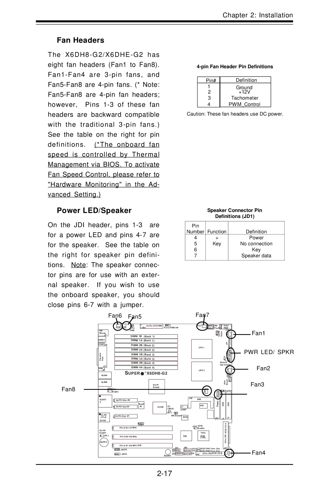
Fan Headers
The
Pin# | Definition |
1 | Ground |
2 | Ground |
+12V | |
3 | Tachometer |
4 | PWM_Control |
Caution: These fan headers use DC power.
Power LED/Speaker
On the JDI header, pins
Fan6 Fan5
Speaker Connector Pin
Definitions (JD1)
Pin |
|
|
Number | Function | Definition |
4 | + | Power |
5 | Key | No connection |
6 |
| Key |
7 |
| Speaker data |
|
|
|
Fan7
Fan8
|
|
|
|
|
|
|
|
|
|
|
|
|
|
|
|
|
|
|
|
|
|
|
|
|
|
|
|
|
|
|
|
|
|
|
|
|
| J32 |
|
|
|
|
| JPF |
|
|
|
|
|
| |||
|
|
|
|
|
|
|
|
|
|
|
|
|
| J1B4 |
|
|
| Force PWR ON | ||||||||
|
|
|
|
|
|
|
| Fan6 Fan5 |
|
|
|
|
| |||||||||||||
|
|
|
|
|
|
|
|
|
|
|
|
|
|
|
|
| ||||||||||
KB/ |
|
|
|
|
|
|
|
| PWR |
|
|
|
|
|
|
|
|
|
|
|
|
|
| |||
Mouse |
|
|
|
|
|
|
|
|
|
|
|
|
|
|
|
|
|
|
|
|
|
|
|
| ||
J9 |
|
|
|
|
|
|
|
| DIMM 1B (Bank 1) |
|
|
|
|
|
|
|
| |||||||||
USB0/1 |
|
|
|
|
|
|
|
|
| DIMM 1A (Bank 1) |
|
|
|
|
|
|
|
| ||||||||
|
|
|
|
|
|
|
|
|
|
|
|
|
|
|
|
|
|
|
|
|
|
|
|
|
| |
COM1 | J6 |
|
|
|
|
|
|
|
| DIMM 2B (Bank 2) |
|
|
|
|
|
|
|
| ||||||||
|
|
|
|
|
|
|
|
|
|
| DIMM 2A (Bank 2) |
|
|
|
|
|
|
|
| |||||||
Parrallel Port |
|
|
|
|
|
|
|
|
|
| DIMM 3B (Bank 3) |
|
|
|
|
|
|
|
| |||||||
|
|
|
|
|
|
|
|
|
|
| DIMM 3A (Bank 3) |
|
|
|
|
|
|
|
| |||||||
|
|
|
|
|
|
|
|
|
|
| DIMM 4B (Bank 4) |
|
|
|
|
|
|
|
| |||||||
J23 |
|
|
|
|
|
|
|
| DIMM 4A (Bank 4) |
|
|
|
|
|
|
|
| |||||||||
VGA |
|
|
|
|
|
|
|
|
|
|
|
|
|
|
|
|
|
| ||||||||
J5 |
|
|
|
|
|
|
|
| SUPER | ® |
|
|
|
|
|
| ||||||||||
|
|
|
|
|
|
|
|
|
|
|
|
|
| |||||||||||||
GLAN1 |
|
|
|
|
|
|
|
|
|
|
|
|
| |||||||||||||
|
|
|
|
|
|
|
|
|
|
|
|
|
|
|
|
|
|
|
|
|
|
|
|
|
|
|
GLAN2 |
|
|
|
|
|
|
|
|
|
|
|
|
|
|
| North |
|
|
|
|
|
|
|
| ||
|
|
|
|
|
|
|
|
|
|
|
|
|
|
|
|
|
|
|
|
|
|
|
|
|
| |
|
|
| JPG1 |
|
|
|
|
|
|
|
|
|
|
| Bridge |
|
|
|
|
|
|
|
| |||
|
|
|
|
|
| VGA |
|
|
|
|
|
|
|
|
|
|
|
|
|
|
|
| ||||
|
|
|
|
|
| Enable |
|
|
|
|
|
|
|
|
|
|
|
|
|
|
| J20 | ||||
|
|
|
|
|
|
|
|
|
|
|
|
|
|
|
|
|
|
|
|
|
|
|
|
|
| |
RAGE- |
|
| 5 |
| X8 |
|
|
|
|
|
|
|
|
|
|
|
|
|
| |||||||
X |
|
|
| 1J |
|
|
|
|
|
| Super |
|
|
|
|
| Clr |
|
|
|
|
| ||||
|
|
|
|
|
| 6 |
|
|
|
|
|
|
|
|
|
|
|
|
|
|
|
| ||||
|
|
|
|
|
| X8 |
|
|
| I/O |
|
|
| ICH5R |
|
|
| J7 |
| |||||||
|
|
|
|
|
| 1J |
|
|
|
|
|
|
|
|
|
|
| CMOS | ||||||||
|
|
|
|
|
|
|
|
|
|
|
|
|
|
|
|
|
|
|
| COM2 | ||||||
|
|
|
|
|
|
|
|
|
|
|
|
|
|
|
|
|
|
|
| JBT1 | JWD | |||||
GLAN |
|
|
| 71 |
| X4 |
|
|
|
|
|
|
|
|
|
| WD Enable | BIOS |
| |||||||
CTLR |
|
|
| J |
|
|
|
|
|
|
|
|
|
|
|
|
|
|
|
|
|
|
|
| ||
82546 |
|
|
|
|
|
|
|
|
|
|
|
|
|
|
|
|
|
|
|
|
|
|
|
| ||
|
|
|
|
|
|
|
|
|
|
|
|
|
|
|
|
|
|
|
|
|
|
|
|
| ||
Fan7 | PWR |
| J24 |
| SMBus |
CPU 1 |
|
CPU 2 |
|
8 |
|
n |
|
a |
|
F |
|
IPMI |
|
SI/O |
|
Fault |
| JP12 |
|
| PWR |
|
|
| ||||||
PW |
|
|
|
|
|
|
| |||||||
|
|
|
|
|
|
|
|
| J1D1 |
| ||||
|
| JP13 | 3rdPS | Alarm |
|
|
| F |
|
|
| |||
|
|
|
|
|
|
|
|
| 1 |
|
|
|
| |
|
|
|
|
|
|
|
|
|
| n |
|
|
|
|
|
|
|
|
|
|
|
|
|
| a |
|
|
|
|
|
|
|
|
|
|
|
|
| JF1 |
|
|
|
| |
|
|
|
|
|
|
|
|
|
|
|
|
|
| |
|
|
|
|
|
|
|
|
|
|
|
|
|
| |
|
|
|
|
|
|
| JP15 JD1 |
|
|
|
|
| ||
|
|
|
|
|
|
|
|
|
|
|
|
|
|
|
|
|
|
|
| Reboot |
|
|
|
|
| ||||
|
|
|
|
| Opt. Enable | |||||||||
|
|
|
|
|
|
|
|
|
| Fan2 |
|
|
|
|
|
|
|
|
|
|
|
|
|
|
|
|
|
| |
|
|
|
|
|
|
|
|
|
| JOH1 |
|
|
|
|
|
|
|
|
|
|
|
|
|
|
|
|
| ||
|
|
|
|
|
|
|
| Alrm Reset |
|
|
|
| ||
|
|
|
|
|
|
|
|
|
|
|
| |||
|
|
|
|
|
|
|
|
|
|
|
|
|
| |
|
|
|
|
| JL1CH Intru | |||||||||
|
| Fan3 |
|
|
|
|
|
|
|
|
|
|
| |
|
| Floppy |
|
|
| IDE2 |
| IDE1 |
|
| ||||
| JP8 |
|
| J4 |
| J3 |
|
| ||||||
Fan1
PWR LED/ SPKR
Fan2
Fan3
|
|
|
|
|
| J11 |
|
|
|
|
|
|
|
|
|
|
|
| A |
|
| ||
|
|
|
|
|
| USB4 |
|
|
|
|
|
|
|
|
|
|
| ||||||
|
|
|
|
|
|
|
|
|
| JPA1 SCSI | SCSICH |
|
| ||||||||||
Enable | 41J | 133 MHz |
|
|
|
|
|
|
|
| Enable |
|
| ||||||||||
|
|
|
|
|
|
|
|
|
|
|
|
| 7902 |
|
|
| |||||||
GLAN |
|
|
|
|
|
|
|
|
|
|
|
|
|
|
|
|
| Ultra320 |
|
| |||
| JPL1 |
|
|
|
|
|
|
|
|
|
|
|
|
|
|
|
|
|
|
| |||
|
| 31J | 100 MHz |
|
|
| PXH |
|
|
|
|
| SCSI |
|
|
| |||||||
|
|
|
|
|
|
|
|
|
|
|
|
|
|
| CTRL |
|
|
| |||||
Battery |
|
|
|
|
|
|
|
|
|
|
|
|
|
|
|
|
|
|
| ||||
|
|
|
|
|
|
|
|
|
|
|
|
|
|
|
|
|
|
| |||||
|
| 21 |
|
|
|
|
|
|
|
|
|
|
|
|
|
|
|
|
| ||||
|
| J |
|
|
|
|
| J22 |
| JS2 |
| JPA2 | SCSI CHA Term. Ena | JA1 |
|
|
| ||||||
|
|
|
|
|
|
|
|
|
|
|
|
|
|
|
|
| |||||||
|
| WOR JWOR |
|
|
|
| SMBUS |
| SATA1 |
| JPA3 | SCSI CHB Term. Ena |
|
|
|
|
| ||||||
|
|
|
|
|
|
|
|
|
|
|
|
|
|
|
|
|
|
|
| Fan4 | |||
|
|
|
| JWOL |
|
| Speaker JD2 | USB2/3 | SATA0 |
| JS1 |
| Ultra 320 SCSI CH B |
|
|
| |||||||
|
| WOL |
|
|
| JA2 |
|
|
| ||||||||||||||
|
|
|
|
|
|
|
|
|
|
|
|
|
|
|
|
|
|
| |||||
Fan4