![]()
![]()
![]()
![]()
![]()
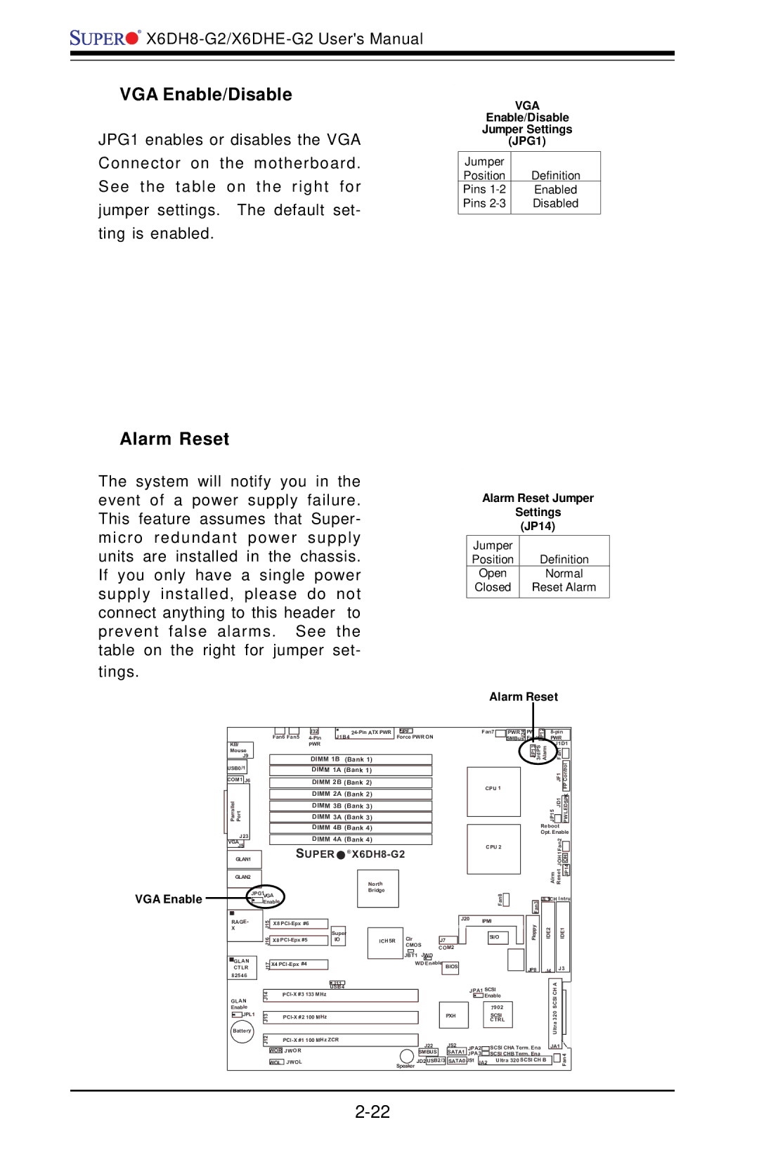
VGA Enable/Disable
JPG1 enables or disables the VGA
Connector on the motherboard.
See the table on the right for
jumper settings. The default set-
ting is enabled.
Alarm Reset
The system will notify you in the event of a power supply failure. This feature assumes that Super- micro redundant power supply units are installed in the chassis. If you only have a single power supply installed, please do not connect anything to this header to prevent false alarms. See the table on the right for jumper set-
tings.
VGA
Enable/Disable
Jumper Settings
(JPG1)
Jumper |
|
Position | Definition |
Pins | Enabled |
Pins | Disabled |
|
|
Alarm Reset Jumper
Settings
(JP14)
Jumper |
|
Position | Definition |
Open | Normal |
Closed | Reset Alarm |
|
|
Alarm Reset
VGA Enable
|
|
|
|
|
|
|
|
|
|
|
|
|
|
|
|
|
|
|
|
|
|
|
|
|
|
|
|
|
|
|
|
|
|
|
|
|
|
|
|
|
|
| J32 |
|
|
|
|
| JPF |
|
|
|
|
|
|
| |||
|
|
|
|
|
|
|
|
| Fan6 Fan5 |
| J1B4 |
|
|
| Force PWR ON | ||||||||||||||
|
|
|
|
|
|
|
|
|
|
|
|
|
|
|
|
|
|
| |||||||||||
| KB/ |
|
|
|
|
|
|
|
|
| PWR |
|
|
|
|
|
|
|
|
|
|
|
|
|
|
| |||
| Mouse |
|
|
|
|
|
|
|
|
|
|
|
|
|
|
|
|
|
|
|
|
|
|
|
|
|
| ||
| J9 |
|
|
|
|
|
|
|
|
| DIMM 1B (Bank 1) |
|
|
|
|
|
|
|
|
| |||||||||
| USB0/1 |
|
|
|
|
|
|
|
|
|
| DIMM 1A (Bank 1) |
|
|
|
|
|
|
|
|
| ||||||||
|
|
|
|
|
|
|
|
|
|
|
|
|
|
|
|
|
|
|
|
|
| ||||||||
|
|
|
|
|
|
|
|
|
|
|
|
|
|
|
|
|
|
|
|
|
|
|
|
|
|
|
|
| |
| COM1 | J6 |
|
|
|
|
|
|
|
|
| DIMM 2B (Bank 2) |
|
|
|
|
|
|
|
|
| ||||||||
|
|
|
|
|
|
|
|
|
|
|
|
| DIMM 2A (Bank 2) |
|
|
|
|
|
|
|
|
| |||||||
| Parrallel Port |
|
|
|
|
|
|
|
|
|
|
|
|
|
|
|
|
|
|
|
|
|
|
|
|
|
|
|
|
|
|
|
|
|
|
|
|
|
|
|
| DIMM 3B (Bank 3) |
|
|
|
|
|
|
|
|
| ||||||||
|
|
|
|
|
|
|
|
|
|
|
|
| DIMM 3A (Bank 3) |
|
|
|
|
|
|
|
|
| |||||||
|
|
|
|
|
|
|
|
|
|
|
|
| DIMM 4B (Bank 4) |
|
|
|
|
|
|
|
|
| |||||||
| J23 |
|
|
|
|
|
|
|
|
| DIMM 4A (Bank 4) |
|
|
|
|
|
|
|
|
| |||||||||
| VGA |
|
|
|
|
|
|
|
|
|
|
|
|
|
|
|
|
|
|
|
| ||||||||
| J5 |
|
|
|
|
|
|
|
|
| SUPER | ® |
|
|
|
|
|
|
| ||||||||||
|
|
|
|
|
|
|
|
|
|
|
|
|
|
|
|
| |||||||||||||
| GLAN1 |
|
|
|
|
|
|
|
|
|
|
|
|
|
|
| |||||||||||||
|
|
|
|
|
|
|
|
|
|
|
|
|
|
|
|
|
|
|
|
|
|
|
|
|
|
|
|
|
|
| GLAN2 |
|
|
|
|
|
|
|
|
|
|
|
|
|
|
|
| North |
|
|
|
|
|
|
|
|
| ||
|
|
|
|
|
|
|
|
|
|
|
|
|
|
|
|
|
|
|
|
|
|
|
|
|
|
|
|
| |
|
|
|
| JPG1 |
|
|
|
|
|
|
|
|
|
|
|
| Bridge |
|
|
|
|
|
|
|
|
| |||
|
|
|
|
|
|
| VGA |
|
|
|
|
|
|
|
|
|
|
|
|
|
|
|
|
| |||||
|
|
|
|
|
|
| Enable |
|
|
|
|
|
|
|
|
|
|
|
|
|
|
| J20 | ||||||
|
|
|
|
|
|
|
|
|
|
|
|
|
|
|
|
|
|
|
|
|
|
|
|
|
|
|
| ||
| RAGE- |
|
|
| 5 |
| X8 |
|
|
|
|
|
|
|
|
|
|
|
|
|
|
| |||||||
| X |
|
|
| 1J |
|
|
|
|
|
|
| Super |
|
|
|
|
| Clr |
|
|
|
|
|
| ||||
|
|
|
|
|
|
|
|
|
|
|
|
|
|
|
|
|
|
|
|
|
|
|
|
|
| ||||
|
|
|
|
|
|
| 6 |
| X8 |
|
|
| I/O |
|
|
| ICH5R |
|
|
| J7 |
|
| ||||||
|
|
|
|
|
|
| 1J |
|
|
|
|
|
|
|
|
|
|
|
|
| CMOS |
|
|
|
| ||||
|
|
|
|
|
|
|
|
|
|
|
|
|
|
|
|
|
|
|
|
|
| COM2 | |||||||
|
|
|
|
|
|
|
|
|
|
|
|
|
|
|
|
|
|
|
|
|
| JBT1 | JWD | ||||||
| GLAN |
|
|
| 7 |
| X4 |
|
|
|
|
|
|
|
|
|
| WD Enable | BIOS |
|
| ||||||||
| CTLR |
|
|
| J1 |
|
|
|
|
|
|
|
|
|
|
|
|
|
|
|
|
|
|
|
|
|
| ||
| 82546 |
|
|
|
|
|
|
|
|
|
|
|
|
|
|
|
|
|
|
|
|
|
|
|
|
| |||
|
|
|
|
|
|
|
|
|
|
|
|
|
|
|
|
|
|
|
|
|
|
|
|
|
| ||||
Fan7 |
|
|
|
| J24 |
| |
|
| PWR |
|
| |||
CPU 1 |
| SMBus |
| ||||
|
|
|
|
| |||
|
|
|
|
| |||
CPU 2 |
|
|
|
|
| ||
|
|
|
|
| |||
|
|
|
|
| |||
|
|
|
|
|
|
|
|
|
|
|
|
|
|
|
|
|
| Fan8 |
|
|
|
|
|
IPMI |
|
|
|
|
| ||
|
|
|
|
| |||
|
|
|
|
|
|
|
|
| SI/O |
|
|
|
|
| |
|
|
|
|
|
|
|
|
|
|
|
|
|
|
|
|
|
|
|
|
|
|
|
|
Fault |
| JP12 |
|
|
|
|
|
|
| ||||
|
| PWR |
| ||||||||||
PW |
|
|
|
|
| ||||||||
| JP13 |
| 3rdPS |
| Alarm |
|
| J1D1 | |||||
|
|
|
|
|
| F |
| ||||||
|
|
|
|
|
|
|
|
|
|
| 1 |
|
|
|
|
|
|
|
|
|
|
|
|
|
|
|
|
|
|
|
|
|
|
|
|
|
|
| JF1 |
| Control |
|
|
|
|
|
|
|
|
|
|
|
|
| FP |
|
|
|
|
|
|
|
|
|
|
|
|
|
|
|
|
|
|
|
|
|
|
|
|
| JD1 |
| SPK |
|
|
|
|
|
|
|
|
| JP15 |
|
| PWLED | |
|
|
|
|
|
|
|
|
|
|
|
| ||
|
|
|
|
|
| Reboot |
|
| |||||
|
|
|
|
|
| Opt. Enable | |||||||
|
|
|
|
|
|
|
|
|
|
|
| Fan2 |
|
|
|
|
|
|
|
|
|
|
|
|
|
| |
|
|
|
|
|
|
|
|
|
|
|
| JOH1 | H |
|
|
|
|
|
|
|
|
|
|
|
|
| O |
|
|
|
|
|
|
|
|
| Alrm Reset |
| JP14 | ||
|
|
|
|
|
|
|
|
|
|
| |||
|
|
|
|
|
|
|
|
|
|
|
|
|
|
|
|
|
|
|
| JL1CH Intru | |||||||
| Fan3 |
|
|
|
|
|
|
|
|
| |||
| Floppy |
|
|
|
| IDE2 |
| IDE1 | |||||
JP8 |
|
|
|
| J4 |
| J3 | ||||||
|
|
|
|
|
| J11 |
|
|
|
|
|
|
|
| A |
|
| |||
|
|
|
|
|
| USB4 |
|
|
|
|
|
|
| |||||||
|
| 4J1 |
|
|
| JPA1 SCSI | SCSICH |
|
|
| ||||||||||
Enable |
|
|
|
| Enable |
|
|
| ||||||||||||
|
|
|
|
|
|
|
|
| 7902 |
|
|
|
| |||||||
GLAN |
|
|
|
|
|
|
|
|
|
|
|
|
| Ultra320 |
|
|
| |||
| JPL1 |
|
|
|
|
|
|
|
|
|
|
| SCSI |
|
|
|
| |||
|
| 13J | 100 MHz |
|
| PXH |
|
|
|
|
|
| ||||||||
|
|
|
|
|
|
|
|
|
|
| CTRL |
|
|
|
| |||||
Battery |
|
|
|
|
|
|
|
|
|
|
|
|
|
|
| |||||
|
|
|
|
|
|
|
|
|
|
|
|
|
|
|
| |||||
|
| 12 |
|
|
|
|
|
|
|
|
|
|
|
|
|
| ||||
|
| J |
|
|
|
| J22 | JS2 | JPA2 |
| SCSI CHA Term. Ena | JA1 |
|
|
|
| ||||
|
|
|
|
|
|
|
|
|
|
|
|
|
|
| ||||||
|
| WOR JWOR |
|
|
|
|
| SATA1 |
|
|
|
|
|
|
| |||||
|
|
|
|
|
|
|
| SMBUS |
| JPA3 |
| SCSI CHB Term. Ena |
|
|
| Fan4 | ||||
|
|
|
|
|
|
| Speaker | USB2/3 |
| JS1 |
| Ultra 320 SCSI CH B |
|
|
| |||||
|
|
|
| JWOL |
|
| JD2 | SATA0 |
|
|
|
|
|
|
| |||||
|
| WOL |
|
| JA2 |
|
|
|
|
|
| |||||||||
|
|
|
|
|
|
|
|
|
|
|
|
|
|
| ||||||
|
|
|
|
|
|
|
|
|
|
|
|
|
|
|
|
|
|
|
|
|