Manuals
/
Brands
/
Computer Equipment
/
Computer Hardware
/
SUPER MICRO Computer
/
Computer Equipment
/
Computer Hardware
SUPER MICRO Computer
X8STI, X8STI-3F, X8STI-F, X8STI-LN4 user manual
2-15
1
39
103
103
Download
103 pages, 5 Mb
Chapter 2: Installation
2-15
1. VGA
Video Connector
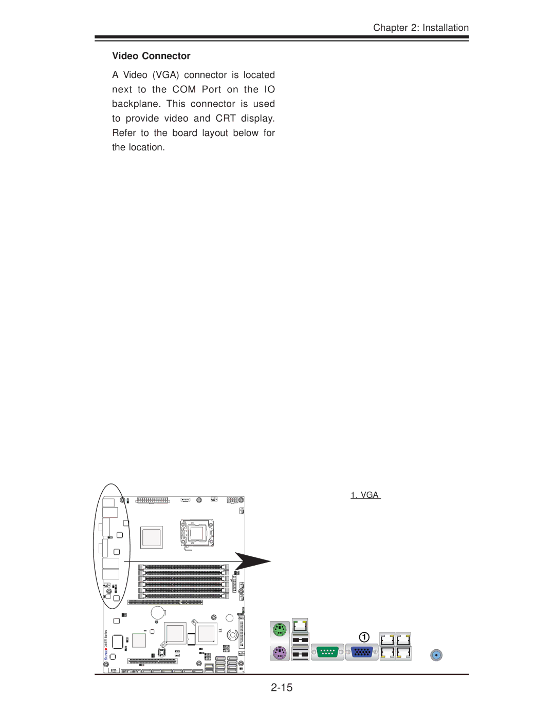
A Video (VGA) connector is located
next to the COM Port on the IO
backplane. This connector is used
to provide video and CRT display.
Refer to the board layout below for
the location.
1
Contents
Main
Printed in the United States of America
Preface
About This Motherboard
iii
Manual Organization
Conventions Used in the Manual:
v
Contacting Supermicro
Headquarters
Europe
Asia-Paci c
vi
Table of Contents
Preface
Chapter 1 Introduction
Chapter 2 Installation
vii
Page
Page
Page
Page
1-4
Chapter 1: Introduction
1-5
X8STi/X8STi-F/X8STi-3F/X8STi-LN4 Jumpers
X8STi/X8STi-F/X8STi-3F/X8STi-LN4 Headers/Connectors
1-6
Page
Page
Page
1-10
X8STi/X8STi-F/X8STi-3F/X8STi-LN4 Users Manual
1-11
1-2 Chipset Overview
Features of the LGA 1366 Processor and the X58 Chipset
1-12
1-3 PC Health Monitoring
Recovery from AC Power Loss
Onboard Voltage Monitoring
Fan Status Monitor with Software
CPU Overheat LED and Control
1-5 Power Supply
1-14
1-6 Super I/O
1-7 Overview of the Winbond WPCM450 Controller (For X8STi-F/ X8STi-3F Only)
Page
Page
2-1
Chapter 2 Installation
2-1 Static-Sensitive Devices
Precautions
Unpacking
2-2
2-2 Processor and Heatsink Installation
Installing an LGA 1366 Processor
2-3
CPU
2-4
Installing a Passive CPU Heatsink (#SNK-P0037)
2-5
Removing the Heatsink
2-6
2-3 Mounting the Motherboard into the Chassis
Tools Needed
Installation Instructions
2-7
2-4 Installing and Removing the Memory Modules
Front View
Top View of DDR3 Slot
CAUTION
Installing & Removing DIMMs
2-8
Maximum Memory Possible
Memory Support
DIMM Module Population Con guration
Chapter 2: Installation
2-9
2-10
2-5 Connectors/IO Ports
Back Panel Connectors and IO Ports
Back Panel Connectors
2-11
2-12
2-13
2-14
2-15
2-16
Front Control Panel
2-17
Front Control Panel Pin De nitions
2-18
2-19
2-20
2-21
2-6 Connecting Cables
2-22
2-23
2-24
2-25
2-26
2-27
2-28
2-29
2-7 Jumper Settings
Explanation of Jumpers
2-30
2-31
2-32
2-33
2-34
2-35
2-8 Onboard Indicators
2-36
2-37
2-38
2-39
2-9 SATA/SAS and Floppy Drive Connections
2-40
3-1
Chapter 3 Troubleshooting
3-1 Troubleshooting Procedures
Before Power On
No Power
No Video
3-2 Technical Support Procedures
3-3
3-3 Frequently Asked Questions
3-4
Warning
3-4 Returning Merchandise for Service
4-1
Chapter 4 BIOS
4-1 Introduction
Starting BIOS Setup Utility
How To Change the Con guration Data
4-2
4-2 Main Setup
4-3
4-4
4-3 Advanced Setup Con gurations
XBOOT Feature
4-5
XProcessor & Clock Options Warning
4-6
4-7
4-8
XAdvanced Chipset Control
XQPI and IMC Con guration
4-9
4-10
4-11
4-12
XIDE / Floppy Con guration
4-13
4-14
XPCI/PnP Con guration
4-15
XSuper IO Device Con guration
4-16
XRemote Access Con guration
4-17
XHardware Health Con guration
4-18
4-19
XACPI Con guration
4-20
XIPMI Con guration (X8STi-F/X8STi-3F Only)
4-21
4-22
XEvent Log Con guration
4-23
4-4 Security Settings
Page
4-25
4-6 Exit Options
XHard Disk Drives
XRemovable Drives
XCD/DVD Drives
4-26
Page
Page
B-1
Appendix B Installing the Windows OS
B-1 Installing the Windows OS to a RAID System
B-2
B-2 Installing the Windows OS to a Non-RAID System
C-1
Appendix C Software Installation Instructions
C-1 Installing Drivers
C-2
C-2 Con guring Supero Doctor III