Chapter 2: Installation
2-6 Connecting Cables
This section provides brief descriptions and
•For information on Backpanel USB and Front Panel USB ports, refer to Page
•For information on COM Port 1 and COM Port 2, please see Page
ATX Power
Pin Definitions (JPW1)
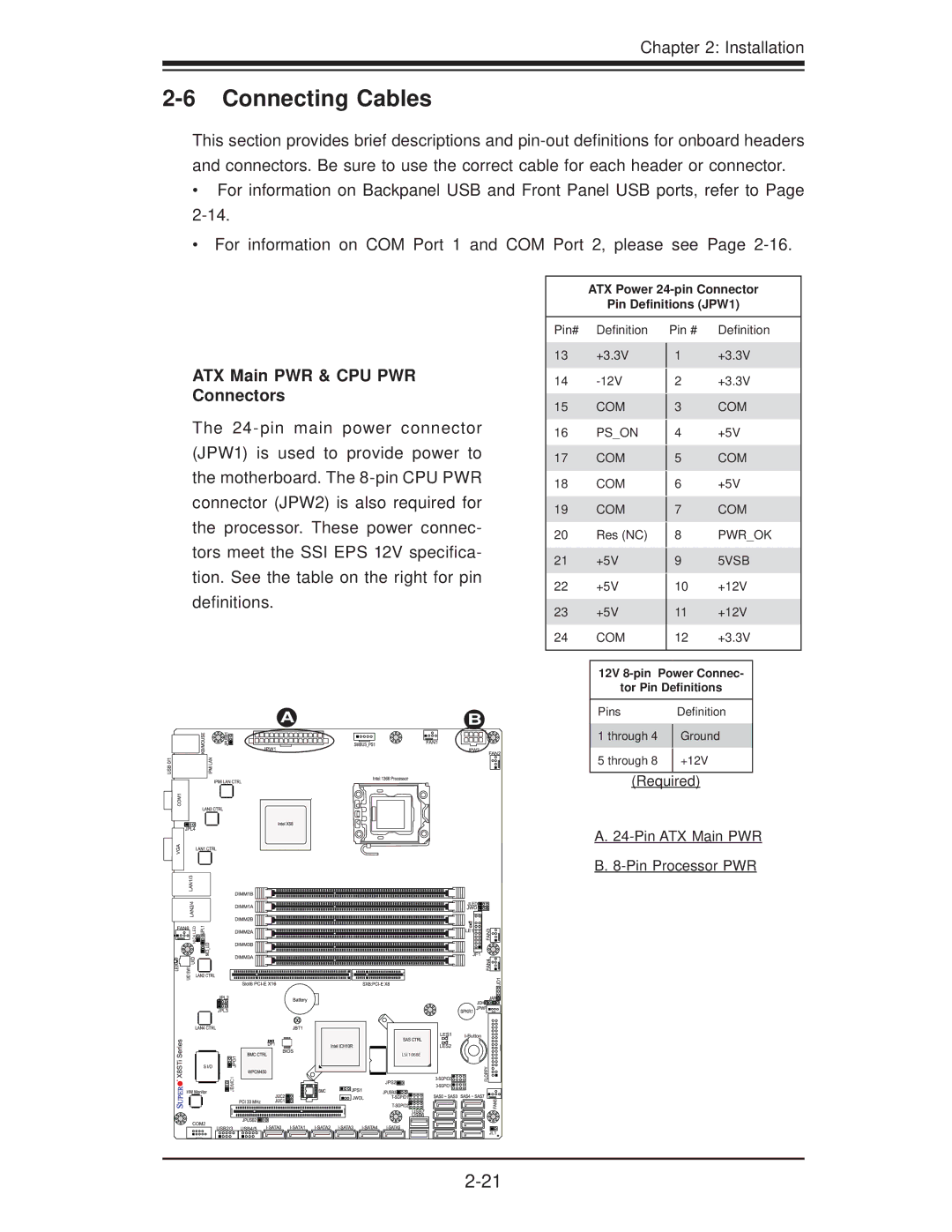
ATX Main PWR & CPU PWR Connectors
The
Pin# Definition
13+3.3V
14
15COM
16PS_ON
17COM
18COM
19COM
20Res (NC)
21+5V
22+5V
23+5V
24COM
Pin # Definition
1+3.3V
2+3.3V
3COM
4+5V
5COM
6+5V
7COM
8PWR_OK
95VSB
10+12V
11+12V
12+3.3V
AB
12V
tor Pin Definitions
Pins |
| Definition |
1 through 4 |
| Ground |
| ||
5 through 8 |
| +12V |
(Required)
A.
B.
NIC4 LED |
![]()
![]()
![]() JBMC1
JBMC1
LSI 1068E