Relay PCA 04523 | Addendum to |
2.4. Heater Control Loop
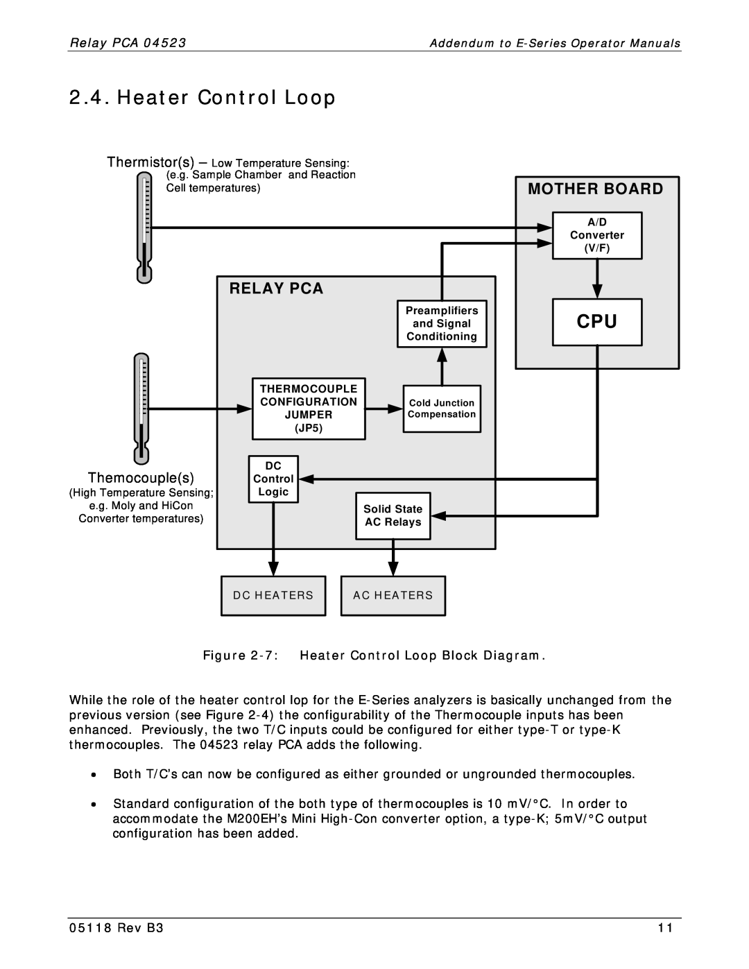
Thermistor(s) – Low Temperature Sensing:
(e.g. Sample Chamber and Reaction
Cell temperatures) |
| MOTHER BOARD | |
|
|
| A/D |
|
|
| Converter |
|
|
| (V/F) |
| RELAY PCA |
|
|
|
| Preamplifiers | CPU |
|
| and Signal | |
|
| Conditioning |
|
| THERMOCOUPLE |
|
|
| CONFIGURATION | Cold Junction |
|
| JUMPER | Compensation |
|
| (JP5) |
|
|
Themocouple(s) | DC |
|
|
Control |
|
| |
(High Temperature Sensing; | Logic |
|
|
e.g. Moly and HiCon |
| Solid State |
|
Converter temperatures) |
|
| |
| AC Relays |
| |
DC HEATERS
AC HEATERS
Figure 2-7: Heater Control Loop Block Diagram.
While the role of the heater control lop for the
∙Both T/C’s can now be configured as either grounded or ungrounded thermocouples.
∙Standard configuration of the both type of thermocouples is 10 mV/°C. In order to accommodate the M200EH’s Mini
05118 Rev B3 | 11 |