Addendum to | Relay PCA 04523 |
2.5. DC Power Supply Test Points
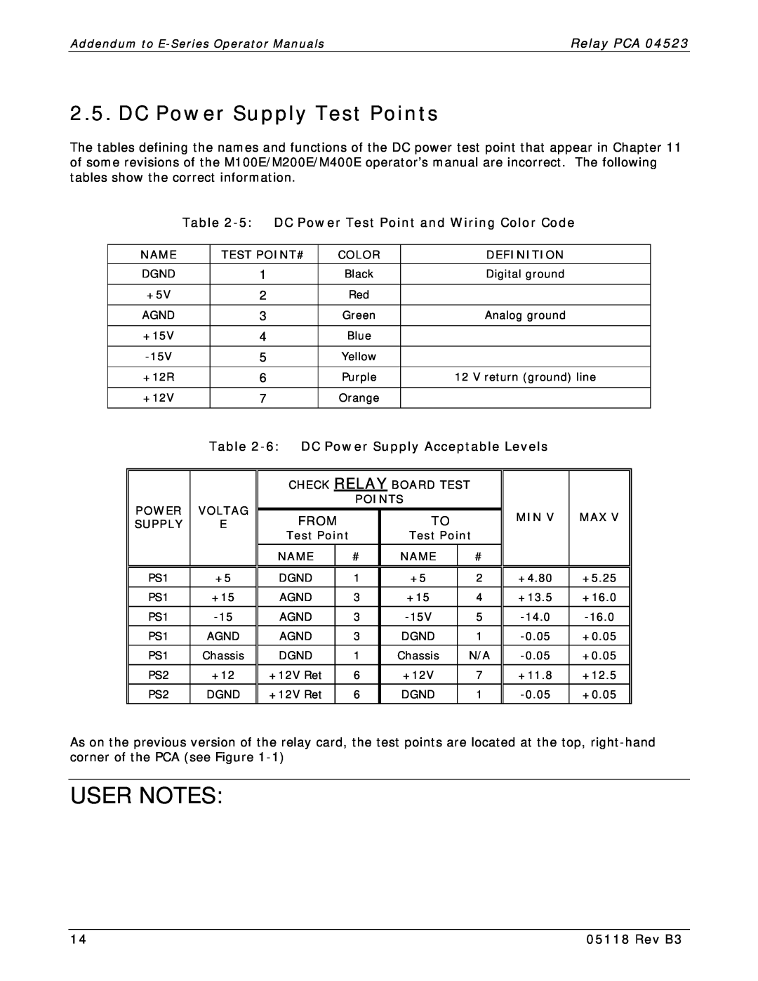
The tables defining the names and functions of the DC power test point that appear in Chapter 11 of some revisions of the M100E/M200E/M400E operator’s manual are incorrect. The following tables show the correct information.
| Table | DC Power Test Point and Wiring Color Code |
|
| |||||||||||
|
|
|
|
|
|
|
|
|
|
|
|
|
|
| |
| NAME |
| TEST POINT# |
| COLOR |
|
|
| DEFINITION |
|
| ||||
|
|
|
|
|
|
|
|
|
|
|
|
|
|
|
|
| DGND |
| 1 |
|
| Black |
|
|
| Digital ground |
|
| |||
|
|
|
|
|
|
|
|
|
|
|
|
|
|
|
|
| +5V |
| 2 |
|
| Red |
|
|
|
|
|
|
|
| |
|
|
|
|
|
|
|
|
|
|
|
|
|
|
|
|
| AGND |
| 3 |
|
| Green |
|
|
| Analog ground |
|
| |||
|
|
|
|
|
|
|
|
|
|
|
|
|
|
|
|
| +15V |
| 4 |
|
| Blue |
|
|
|
|
|
|
|
| |
|
|
|
|
|
|
|
|
|
|
|
|
|
|
|
|
|
| 5 |
|
| Yellow |
|
|
|
|
|
|
|
| ||
|
|
|
|
|
|
|
|
|
|
|
|
|
|
| |
| +12R |
| 6 |
|
| Purple |
|
| 12 V return (ground) line | ||||||
|
|
|
|
|
|
|
|
|
|
|
|
|
|
|
|
| +12V |
| 7 |
|
| Orange |
|
|
|
|
|
|
|
| |
|
|
|
|
|
|
|
|
|
|
|
|
|
| ||
|
| Table |
|
| |||||||||||
|
|
|
|
|
|
|
|
|
|
|
|
| |||
|
|
|
|
| CHECK RELAY BOARD TEST |
|
|
|
| ||||||
| POWER | VOLTAG |
|
|
| POINTS |
|
|
|
|
|
| |||
|
|
|
|
|
|
|
|
| MIN V |
| MAX V |
| |||
|
| FROM |
| TO |
|
|
|
| |||||||
| SUPPLY |
| E |
|
|
|
|
|
| ||||||
|
|
|
|
|
|
|
|
|
| ||||||
|
|
|
|
| Test Point |
| Test Point |
|
|
|
| ||||
|
|
|
|
|
|
|
|
|
|
|
|
|
|
| |
|
|
|
|
| NAME | # |
| NAME |
| # |
|
|
|
| |
|
|
|
|
|
|
|
|
|
|
|
|
| |||
|
|
|
|
|
|
|
|
|
|
|
| ||||
| PS1 | +5 |
| DGND | 1 | +5 |
| 2 | +4.80 |
| +5.25 |
| |||
|
|
|
|
|
|
|
|
|
|
|
|
| |||
| PS1 | +15 |
| AGND | 3 | +15 |
| 4 | +13.5 |
| +16.0 |
| |||
|
|
|
|
|
|
|
|
|
|
|
|
|
| ||
| PS1 |
| AGND | 3 |
|
| 5 |
|
| ||||||
|
|
|
|
|
|
|
|
|
|
|
|
|
| ||
| PS1 | AGND |
| AGND | 3 |
| DGND |
| 1 |
| +0.05 |
| |||
|
|
|
|
|
|
|
|
|
|
|
|
| |||
| PS1 | Chassis |
| DGND | 1 | Chassis |
| N/A |
| +0.05 |
| ||||
|
|
|
|
|
|
|
|
|
|
|
|
|
| ||
| PS2 | +12 |
| +12V Ret | 6 |
| +12V |
| 7 | +11.8 |
| +12.5 |
| ||
|
|
|
|
|
|
|
|
|
|
|
|
|
| ||
| PS2 | DGND |
| +12V Ret | 6 |
| DGND |
| 1 |
| +0.05 |
| |||
|
|
|
|
|
|
|
|
|
|
|
|
|
|
|
|
As on the previous version of the relay card, the test points are located at the top,
USER NOTES:
14 | 05118 Rev B3 |