Addendum to | Relay PCA 04523 |
2.3. Status LEDs & Watch Dog Circuitry
Like the previous version, the status LED’s on the Relay PCA 04523 includes thirteen LEDs that indicate the status of the analyzer’s heaters, valves and other general operating conditions. Since the functions represented by these LED differs from model to model, check your M100E/M200E/M400E operator’s manual for their exact assignments (this can normally be found in the section on Electronic Theory of Operation).
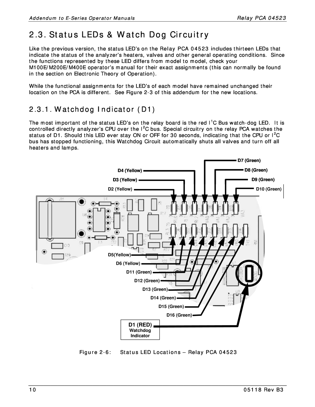
While the functional assignments for the LED’s of each model have remained unchanged their location on the PCA is different. See Figure
2.3.1. Watchdog Indicator (D1)
The most important of the status LED’s on the relay board is the red I1C Bus
| D7 (Green) |
D4 (Yellow) | D8 (Green) |
D3 (Yellow) | D9 (Green) |
D2 (Yellow) | D10 (Green) |
D5(Yellow)![]()
D6 (Yellow)
D11 (Green)
D12 (Green)
D13 (Green)
D14 (Green)
D15 (Green)
D16 (Green)
D1 (RED)
Watchdog
Indicator
Figure 2-6: Status LED Locations – Relay PCA 04523
10 | 05118 Rev B3 |