Telenetics 2185
Function Switch Three
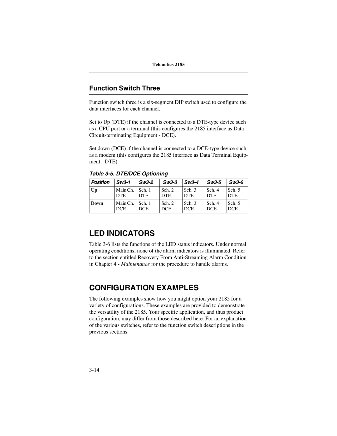
Function switch three is a
Set to Up (DTE) if the channel is connected to a
Set down (DCE) if the channel is connected to a
Table 3-5. DTE/DCE Optioning
Position | ||||||
|
|
|
|
|
|
|
Up | Main Ch. | Sch. 1 | Sch. 2 | Sch. 3 | Sch. 4 | Sch. 5 |
| DTE | DTE | DTE | DTE | DTE | DTE |
|
|
|
|
|
|
|
Down | Main Ch. | Sch. 1 | Sch. 2 | Sch. 3 | Sch. 4 | Sch. 5 |
| DCE | DCE | DCE | DCE | DCE | DCE |
|
|
|
|
|
|
|
LED INDICATORS
Table
CONFIGURATION EXAMPLES
The following examples show how you might option your 2185 for a variety of configurations. These examples are provided to demonstrate the versatility of the 2185. Your specific application, and thus product configuration, may differ from those described here. For an explanation of the various switches, refer to the function switch descriptions in the previous sections.
