Telenetics 2185
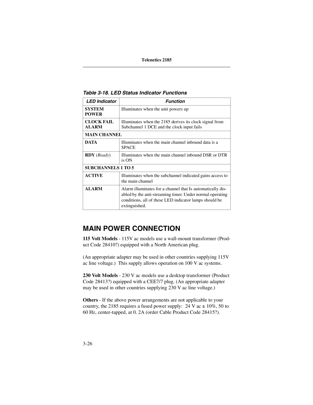
Table 3-18. LED Status Indicator Functions
LED Indicator | Function |
|
|
SYSTEM | Illuminates when the unit powers up |
POWER |
|
|
|
CLOCK FAIL | Illuminates when the 2185 derives its clock signal from |
ALARM | Subchannel 1 DCE and the clock input fails |
|
|
MAIN CHANNEL | |
|
|
DATA | Illuminates when the main channel inbound data is a |
| SPACE |
|
|
RDY (Ready) | Illuminates when the main channel inbound DSR or DTR |
| is ON |
|
|
SUBCHANNELS 1 TO 5 | |
|
|
ACTIVE | Illuminates when the subchannel indicated gains access to |
| the main channel |
|
|
ALARM | Alarm illuminates for a channel that Is automatically dis- |
| abled by the |
| conditions, all of these LED indicator lamps should be |
| extinguished. |
|
|
MAIN POWER CONNECTION
115Volt Models - 115V ac models use a
(An appropriate adapter may be used in other countries supplying 115V ac line voltage.) This supply allows operation on 100 V ac systems.
230 Volt Models - 230 V ac models use a desktop transformer (Product Code 28413?) equipped with a CEE7/7 plug. (An appropriate adapter may be used in other countries supplying 230 V ac line voltage.)
Others - If the above power arrangements are not applicable to your country, the 2185 requires a fused power supply: 24 V ac ± 10%, 50 to 60 Hz,